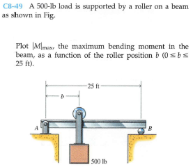
C8-49 A 500-lb load is supported by a roller on a beam as shown in Fig. Plot |Mmax, the maximum bending moment in the beam, as a function of the roller position b (0 sbs 25 ft). -25 ft- A B 500 lb


Q: Part 1 Correct For the simply supported beam subjected to the loading shown, derive equations for…
A:
Q: Draw the shear-force and bending-moment diagram for the beam shown. Assume the upward reaction…
A: Given: a=5 ft and b=3.4 ft Value of P=25 kips Value of w=1.1 kips/ft Hence total downward force:…
Q: *RII-4. Determine the maximum bending stres in the handle of the cable cutter at section a-a. A…
A: For solution refer below images.
Q: C8-49 A 500-lb load is supported by a roller on a beam as shown in Fig. Show that the maximum…
A:
Q: at the top to 90 kPa at the bottom. As an additional support, it is anchored at depth y = 2 m. with…
A: cantiliver retaining wall is subjected to a soil pressure linearly varying from zero at the top to…
Q: Draw the free body diagram of the beam. 30° 0, -20° 0.8 m 0.3 W
A: The free body diagram of the beam is as follows:
Q: Q4: A simply supported I-beam of (2 m) span carries a central load of (4 kN). The load acts through…
A: Given Datal=2mP=4kNθ=30°
Q: (a) Figure 5 shows two shafts connected by the gears. End A of the shaft is connected to a motor…
A: The gear drive is used to transmit the power from the one shaft to another . It is a transmission…
Q: Draw the shear force and bending moment diagram for the loaded beam shown below. Also mark the…
A:
Q: Il-15. Members ABC and BD of the counter chair are rigidly connected at B and the smooth collar at D…
A:
Q: Calculate the shear force and bending moment for the simply supported beam of length 8m with the…
A:
Q: A beam ABCDE is 5 m in length and loaded as shown in Fig.3. Draw the S.F. and B.M. diagrams for the…
A:
Q: ure. The bending moment at 0.5 m from the support is approximately
A: To determine the bending moment at 0.5 from support.
Q: A vertical shaft 25 mm diameter and 0.75 m long is mounted in long bearings and carries a pulley of…
A: Given data: The diameter of the shaft is d = 25 mm = 0.025 mThe length of the shaft is L = 0.75 mThe…
Q: Determine the value of Elv (in Ib ft³ )at midspan for the beam loaded by two concentrated forces if…
A:
Q: The simple beam shown supports the uniformly distributed load with intensity wo = 300 N/m. The span…
A:
Q: Draw shear and bending moment diagrams for the beamin Figure 3.14b, which carries a uniformly…
A: givencantilever beam as shown below
Q: C7-31 Athree-bar truss is loaded and supported as shown in Fig. a function of angle e (0 ses 90°).…
A: Understand the following configuration for the triangular truss. From the given triangular truss.
Q: Draw the shear force and the bending moment diagrams for the simply supported beam loaded with a…
A: Shear force diagram represents shear force at every section of the beam. Shear force at any…
Q: -2 m + -2 m- B 120 N-m Problem 5/121
A: As per bartleby guidelines we are allowed to solve only 1st question if multiple questions are…
Q: 7-27 For the cantilever beam shown in Fig. P7-27, write equa- tipns for the shear force V, and the…
A: Given data: The load applied at end A is F = 1000 lb. The length of beam is L = 4 ft. Consider a…
Q: A propped cantilever beam has flexural rigidity EI = 2.5 MN•m2. When the loads shown are applied to…
A:
Q: R: 1 egram egram gram egram gram
A: Solution is attached below
Q: b=0.05m. BEAH BY. SOLVE Foh THe VERT ICAL DISPLACEHENT OF THE BEAM (I,) a) STATE THE GOV'N ER'N OF…
A: A moment is a movement of the body when a body is rotating on an axis. The moment is also known as…
Q: The shear-force diagram for a beam isshown in the figure. Assuming that no couples actas loads on…
A: Given data as per question The total length of the beam =24 ft Calculations Calculations the…
Q: E 1.0m- W₁ -2.0m- Situation 3: W₁ = 4 kN - m
A: Given that: W1 = distributed force = 4 kN/m It is required to determine the maximum deflection of…
Q: For the beam shown, find the reactions at the supports and plot the shear-force and bending-moment…
A:
Q: 4 kN 4 kN/m 10 kN.m to A D E 3 m→|-2 m-|<-3 m→|-2 m-
A: The reaction forces calculated as :…
Q: Under cruising conditions, the distributed load acting on the wing of a small airplane has the…
A:
Q: 2. FROM THE GIVEN BEAK COMPUTE THE FF- a REACTIONS @ A B b. SHEAR AD MOMENT AT C DRAVW 7HE SHIEAR 3…
A: Hi. as you have posted multiple questions and have not specified which question needs to be solved,…
Q: 1 Draw shear and moment diagram. Det. max. V and max. M 2. Draw loading and moment diagram given the…
A:
Q: Example The beam ABC is loaded via a 500 N.m couple and a 600 N force as shown. The beam is…
A: Static equilibrium: A body is said to be in static equilibrium if it satisfies the following…
Q: 7-81. Draw the shear and moment diagrams for the beam. Problem 7-81 6 ft 200 lb/ft 6 ft
A: Draw the free-body diagram of the beam. Apply force equilibrium in horizontal direction. HB=0…
Q: 8. For the beam shown, derive the expressions for V and M, and draw the shear force and bending…
A:
Q: 20 kN 10 kN/m 10 kN 10 kN-m 3 8 z (m) 7 15 2.
A: shear force A shear force is a force applied perpendicular to a surface, in opposition to an offset…
Q: The side rod of the engine in the figure is 8ft long and weighs 100lb. the cranks AD and BC are of…
A: We have, Length of the rod, l=8ft.=2.4384m Weight of rod, W=100lb=444.822N Let ω be the uniformly…
Q: A girder ABCDE bears on a wall for a length BC and is prevented from overturning by a holding-down…
A:
Q: 31 A beam is loaded and supported as shown in Fig. P7-31. Using the coordinate axes shown, write…
A:
Q: 6.43-6.56 Construct the shear force and bending moment diagrams for the beam shown by the area…
A: SFD is one degree higher than the loading diagram and BMD is one degree higher than SFD. If at any…
Q: C7-32 A truss is loaded and supported as shown in Fig. Plot the forces in members BC, BG, and GH of…
A: Draw a free-body diagram of the truss, Apply force equilibrium in a horizontal direction,…
Q: -w/m H H A WR WR 19 13
A:
Q: 6.43-6.56 Construct the shear force and bending moment diagrams for the beam shown by the area…
A: Shear force: It is nothing but the force in transverse direction acting on a beam cross-section at…
Q: The bending moment reaction at the fixed support (in N.M) is 200 N/m A IB -3 m 3 m
A:
Q: For the given simply supported beam: If P=56 N/m, W353 N/m, L1-6.63 meter, L2-2.99 meter W L1 L2…
A:
Q: 40 kN 1 20 kN Find slope and deflection at D C V DV = 100 MN. m A B 3.0 m 1.5 m 1.5 m
A:
Q: An overhanging beam is loaded as indicated. In order to accommodate communication cables to be…
A: ◆ Determine the reactions at the support A and B using the equilibrium equations and draw the shear…
Q: A car parking roof with cantilever beam of length 6 m carrying point loads of 12 kN and 8 kN at 1.5…
A: With given information, following configuration diagram is drawn for a cantilever beam 'AB'. Here,…
Q: Pr4-30P) Draw shear force and bending moment diagrams of the beam. Hint : Calculate reaction forces.…
A:
Q: The beam shown in the photo is used to support a portion of the overhang for the entranceway of the…
A: Shear force and Bending moment diagram are very important tools. Sign Convention for SFD 1) Right…

Step by step
Solved in 2 steps with 6 images

- A frame ABCD is constructed of steel wide-flange members (W8 x 21; E = 30 x ID6 psi) and subjected to triangularly distributed loads of maximum intensity q0acting along the vertical members (see figure). The distance between supports is L = 20 ft and the height of the frame is h = 4 ft. The members are rigidly connected at B and C. Calculate the intensity of load q0 required to produce a maximum bending moment of 80 kip-in. in the horizontal member BC. If the load q0 is reduced to one-half of the value calculated in part (a), what is the maximum bending moment in member BC? What is the ratio of this moment to the moment of 80 kip-in. in part (a)?The horizontal beam ABC of an oil-well pump has the cross section shown in the figure. If the vertical pumping force acting at end C is 9 kips and if the distance from the line of action ofthat force to point B is 16 ft, what is the maximum bending stress in the beam due to the pumping force?A heavy object of weight W is dropped onto the midpoint of a simple beam AB from a height h (see figure). Obtain a formula for the maximum bending stress ^ma* due to tne filing weight in terms of h, st, and 5st, where it is the maximum bending stress and Sstis the deflection at the midpoint when the weight W acts on the beam as a statically applied load. Plot a graph of the ratio o"max/ö"it (that is, the ratio of the dynamic stress to the static stress) versus the ratio iifS^r(Let h/S^ vary from 0 to 10.)
- Find an expression for required moment MA(in terms of q and L) that will result in rotation êB= 0 due to MAand q loadings applied at the same time. Also, what is the resulting net rotation at support A?A beam supporting a uniform load of intensity q throughout its length rests on pistons at points A, C and B (sec figure). The cylinders are filled with oil and are connected by a tube so that the oil pressure on each piston is the same. The pistons at A and B have diameter d1and the piston at C has diameter D2. (a) Determine the ratio of d2to d1so that the largest bending moment in the beam is as small as possible. Under these optimum conditions, what is the largest bending moment Mmaxin the beam? What is the difference in elevation between point C and the end supports?A rectangular beam with semicircular notches, as shown in part b of the figure, has dimensions h = 120 mm and h1= 100 mm. The maximum allowable bending stress in the plastic beam is emix = 6 M Pa, and the bending moment is M = 150 N · m. Determine the minimum permissible width bminof the beam.
- Find an expression for required moment MA(in terms of q and L) that will result in rotation 9B= 0 due to MAand q loadings applied at the same time. Also, what is the resulting net rotation at support A?Find required distance d (in terms of L) so that rotation Ss= 0 is due to M and q loadings applied at the same time. Also, what is the resulting net rotationA cant i levé r b ea m i s supported by a tie rod at B as shown. Both the tie rod and the beam are steel with E = 30 x 106 psi. The tie rod is just taut before the distributed load q = 200 lb/ft is applied. Find the tension force in the tie rod. Draw shear-force and bending-moment diagrams for the beam, labeling all critical ordinates.
- Divide the plane frame structure shown in the image into suitable parts for analytical examination and draw the free-body diagrams of the parts. Additionally, determine the shear force and bending moment diagrams of the structure. F = 10 kN and a = 2 m. There is a roller support on the left edge and a fixed support at the bottom.Determine the shear force, V and its bending moment, M. kindly provide the SFD and BMDA load of 100 kN, followed by another load of 50 kN, at a distance of 10 metres, advances across a girder with a 100-metre span. Obtain an expression for the maximum bending moment at a section of the girder at a distance of z metres from an abutment. Please provide solutions. Answer is z(140-1.5z) for z< (100/3)m;(100-z)(1.5z-5) for z>(100/3) m.