7.15 The transistor in the circuit of Fig. P7.15 is biased at a de collector current of 0.3 mA. What is the voltage gain? (Hint: Use Thévenin's theorem to convert the circuit to the form in Fig. 7.6.) +5 V 10 kΩ 10 kM
7.15 The transistor in the circuit of Fig. P7.15 is biased at a de collector current of 0.3 mA. What is the voltage gain? (Hint: Use Thévenin's theorem to convert the circuit to the form in Fig. 7.6.) +5 V 10 kΩ 10 kM

Delmar's Standard Textbook Of Electricity
7th Edition
ISBN:9781337900348
Author:Stephen L. Herman
Publisher:Stephen L. Herman
Chapter29: Dc Generators
Section: Chapter Questions
Problem 16RQ: Explain the difference between cumulative- and differential-compounded connections.

Related questions

Question
100%
Hi, I need an answer for question 7.15
Thank you
Transcribed Image Text:Microelectronic_Circuits_by_Sedra_Smith.pdf - Foxit Reader
O
File
Home
Comment
Fill & Sign
View
Form
Protect
Share
Connect
Help
O Tell me what you want to do...
7.15
O SnapShot
B Clipboard -
O 200%
A Link
O File Attachment
O Fit Page
T
D Fit Width
TI
Rotate Left
A Bookmark
e Image Annotation
Hand Select
Actual
D Fit Visible
Reflow
L- Rotate Right
Typewriter Highlight
O Audio & Video
Size
Tools
View
Comment
Links
Insert
Microelectronic_Circuits_...
福听PDF转Word
Start
Lq. (7.11). DIIOW Ulat nc gamm CAPITSSION Cllangts to
(g) A,
-500 V/V, P = 2.0 V
=
-I RV,
(Vcc – Vee) /Vr
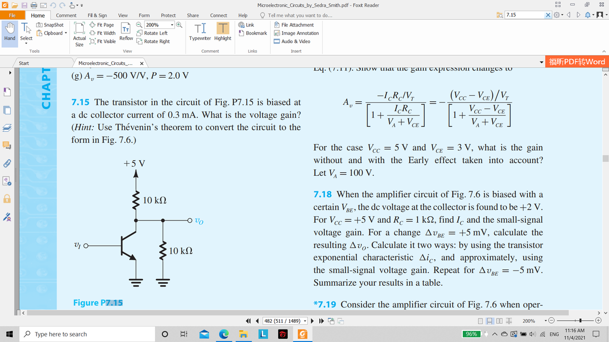
7.15 The transistor in the circuit of Fig. P7.15 is biased at
А,
IR.
1+
Vcc – VCE
1+
a de collector current of 0.3 mA. What is the voltage gain?
(Hint: Use Thévenin's theorem to convert the circuit to the
form in Fig. 7.6.)
V+VCE -
VA+VCE
А
For the case Vcc = 5 V and VCE = 3 V, what is the gain
without and with the Early effect taken into account?
+5 V
Let V, = 100 V.
7.18 When the amplifier circuit of Fig. 7.6 is biased with a
certain VRF, the dc voltage at the collector is found to be +2 V.
For Vcc =+5 V and R. =1 k2, find I, and the small-signal
voltage gain. For a change AV BE
10 kΩ
BE >
O Vo
CC
+5 mV, calculate the
resulting Avo. Calculate it two ways: by using the transistor
exponential characteristic Aic, and approximately, using
the small-signal voltage gain. Repeat for AvBE =
10 kΩ
= -5 mV.
-
Summarize your results in a table.
Figure PZ.15
*7.19 Consider the amplifier circuit of Fig. 7.6 when oper-
11 482 (511 / 1489)
200%
11:16 AM
O Type here to search
日
96%
1 4) G ENG
11/4/2021
CHAPT
>
Transcribed Image Text:Microelectronic_Circuits_by_Sedra_Smith.pdf - Foxit Reader
O
File
Home
Comment
Fill & Sign
View
Form
Protect
Share
Connect
Нер
O Tell me what you want to do...
Figure 7.6
O SnapShot
A Clipboard -
O 200%
A Link
O File Attachment
O Fit Page
TT
D Fit Width
TI
Rotate Left
A Bookmark
e Image Annotation
Hand Select
Actual
D Fit Visible
Reflow
L Rotate Right
Typewriter Highlight
O Audio & Video
Size
Tools
View
Comment
Links
Insert
福听PDF转Word
Start
Microelectronic_Circuits_...
Rc
+
UCE
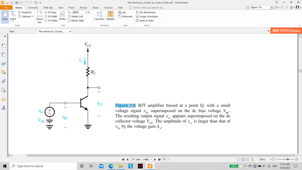
Figure 7.6 BJT amplifier biased at a point
voltage signal v superimposed on the de bias voltage VRp:
The resulting output signal v appears superimposed on the de
collector voltage Ver: The amplitude of v, is larger than that of
v, by the voltage gain A,.
with a small
Upe
BE
UBE
V BE
CE *
11 ( 377 (406 / 1489)
目昌目非
200%
11:15 AM
O Type here to search
96%
1 4) G ENG
11/4/2021
Expert Solution
This question has been solved!
Explore an expertly crafted, step-by-step solution for a thorough understanding of key concepts.

This is a popular solution!

Trending now
This is a popular solution!

Step by step
Solved in 2 steps with 1 images

Knowledge Booster


Learn more about
Need a deep-dive on the concept behind this application? Look no further. Learn more about this topic, electrical-engineering and related others by exploring similar questions and additional content below.Recommended textbooks for you
Delmar's Standard Textbook Of Electricity
Electrical Engineering
ISBN:
9781337900348
Author:
Stephen L. Herman
Publisher:
Cengage Learning
Delmar's Standard Textbook Of Electricity
Electrical Engineering
ISBN:
9781337900348
Author:
Stephen L. Herman
Publisher:
Cengage Learning