circuitry is not shown. Replace the BJT with its hybrid- 7.52 Figure P7.52 shows a particular configuration of BJT equivalent circuit of Fig. 7.24(a). Find the input resistance amplifiers known as "emitter follower." The bias arrangement Rv,li, the voltage transmission from source to amplifieris not shown. Replace the BJT with its T equivalent-circuit S- MultisimPSpice; * difficult problem; ** more difficult; ***- very challenging: D design problem 488 Chapter 7 Transistor Amplifiers model of Fig. 7.26(b). Show that 7.54 In the circuit shown in Fig. P7.54, the transistor has a B of 200. What is the de voltage at the collector? Replacing the BJT with one of the hybrid-r models (neglecting r), draw the equivalent circuit of the amplifier. Find the input resistances R and R, and the overall voltage gain (vJv). For an output signal of 10.4 V, what values of v, and v, are required? R.-- (9 + 1)(, +R.) +SV +1,5V )10 mA 10 kf I kl R Rc 100 Figure P7.52
circuitry is not shown. Replace the BJT with its hybrid- 7.52 Figure P7.52 shows a particular configuration of BJT equivalent circuit of Fig. 7.24(a). Find the input resistance amplifiers known as "emitter follower." The bias arrangement Rv,li, the voltage transmission from source to amplifieris not shown. Replace the BJT with its T equivalent-circuit S- MultisimPSpice; * difficult problem; ** more difficult; ***- very challenging: D design problem 488 Chapter 7 Transistor Amplifiers model of Fig. 7.26(b). Show that 7.54 In the circuit shown in Fig. P7.54, the transistor has a B of 200. What is the de voltage at the collector? Replacing the BJT with one of the hybrid-r models (neglecting r), draw the equivalent circuit of the amplifier. Find the input resistances R and R, and the overall voltage gain (vJv). For an output signal of 10.4 V, what values of v, and v, are required? R.-- (9 + 1)(, +R.) +SV +1,5V )10 mA 10 kf I kl R Rc 100 Figure P7.52

Delmar's Standard Textbook Of Electricity
7th Edition
ISBN:9781337900348
Author:Stephen L. Herman
Publisher:Stephen L. Herman
Chapter29: Dc Generators
Section: Chapter Questions
Problem 16RQ: Explain the difference between cumulative- and differential-compounded connections.

Related questions

Question
100%
Hi, I need the answer for question 7.52
Your help would mean so much to me
Transcribed Image Text:Microelectronic_Circuits_by_Sedra_Smith.pdf - Foxit Reader
O
File
Home
Comment
Fill & Sign
View
Form
Protect
Share
Connect
Help
O Tell me what you want to do...
7.26(b)
O SnapShot
B Clipboard -
O 100%
O Fit Page
T
D Fit Width
A Link
A Bookmark
U File Attachment
TI
e Image Annotation
O Audio & Video
Rotate Left
Hand Select
Actual
Reflow
Typewriter Highlight
D Fit Visible
Rotate Right
Size
Tools
View
Comment
Links
Insert
福听PDF转Word
Start
Microelectronic_Circuits_...
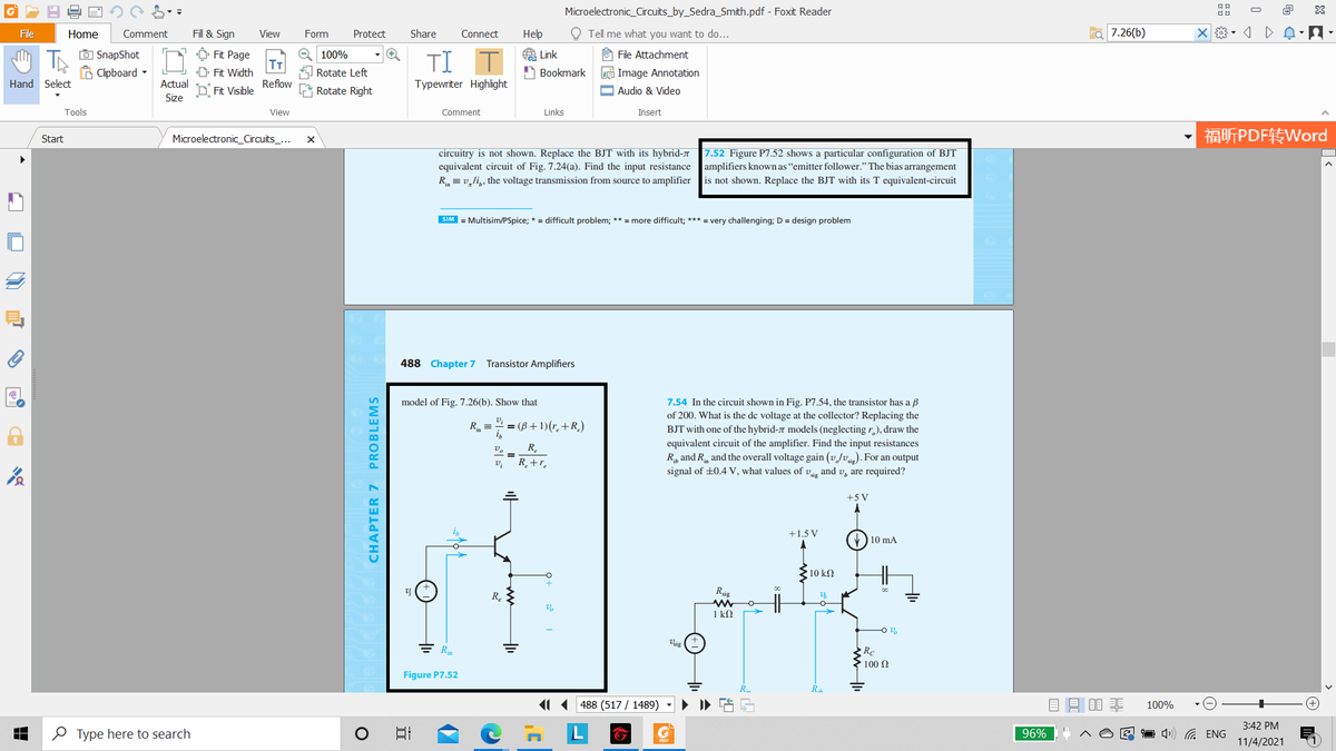
7.52 Figure P7.52 shows a particular configuration of BJT
circuitry is not shown. Replace the BJT with its hybrid-7
equivalent circuit of Fig. 7.24(a). Find the input resistance
R = v,li,, the voltage transmission from source to amplifier
amplifiers known as “emitter follower." The bias arrangement
is not shown. Replace the BJT with its T equivalent-circuit
SIM = Multisim/PSpice; * = difficult problem; ** = more difficult; *** = very challenging; D = design problem
488 Chapter 7 Transistor Amplifiers
model of Fig. 7.26(b). Show that
7.54 In the circuit shown in Fig. P7.54, the transistor has a B
of 200. What is the de voltage at the collector? Replacing the
R =
= (B+ 1)(r. +R.)
BJT with one of the hybrid-7 models (neglecting r,), draw the
equivalent circuit of the amplifier. Find the input resistances
R, and R and the overall voltage gain (vJv). For an output
signal of +0.4 V, what values of v, and v, are required?
R.
R_+r.
+5 V
+1.5 V
) 10 mA
10 kΩ
Rig
R.
1 k2
ig
Rc
► 100 2
Figure P7.52
11(488 (517 / 1489)
目目目非
100%
3:42 PM
O Type here to search
日
L
1 4») G ENG
96%
11/4/2021
CHAPTER 7 PROBLEMS
Transcribed Image Text:Microelectronic_Circuits_by_Sedra_Smith.pdf - Foxit Reader
O
File
Home
Comment
Fill & Sign
View
Form
Protect
Share
Connect
Нер
O Tell me what you want to do...
7.26(b)
O SnapShot
B Clipboard -
A Link
Ô Fit Page
T
D Fit Width
e 150%
O File Attachment
TI
Rotate Left
A Bookmark
e Image Annotation
Hand Select
Actual
Reflow
Typewriter Highlight
D Fit Visible
Rotate Right
O Audio & Video
Size
Tools
View
Comment
Links
Insert
福听PDF转Word
Start
Microelectronic_Circuits_...
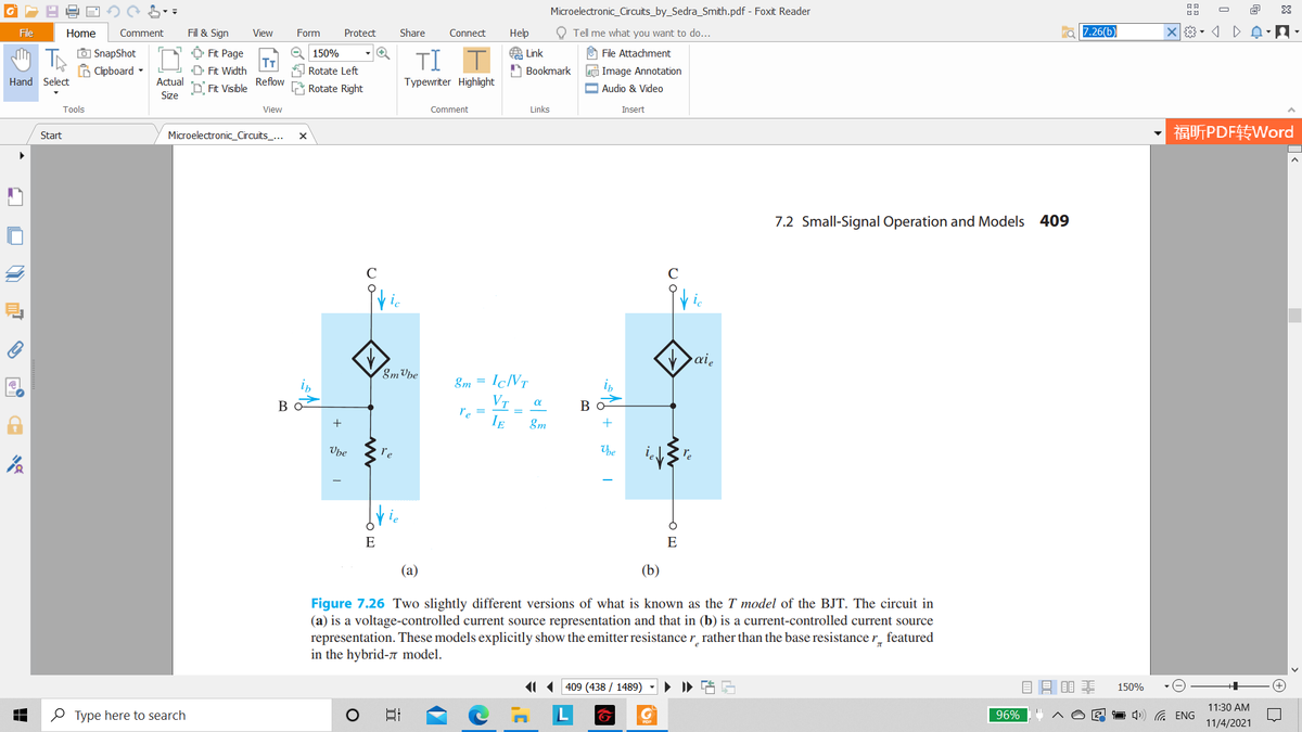
7.2 Small-Signal Operation and Models 409
C
ic
ai,
8m Vbe
8m =
IÇNT
VT
re =
IE
Bo
Во
&m
Vbe
re
he
E
E
(а)
(b)
Figure 7.26 Two slightly different versions of what is known as the T model of the BJT. The circuit in
(a) is a voltage-controlled current source representation and that in (b) is a current-controlled current source
representation. These models explicitly show the emitter resistance r rather than the base resistance r_ featured
in the hybrid-n model.
11 409 (438 / 1489)
目昌目非
150%
11:30 AM
O Type here to search
日
96%
1 4) G ENG
11/4/2021
Expert Solution
This question has been solved!
Explore an expertly crafted, step-by-step solution for a thorough understanding of key concepts.

This is a popular solution!

Trending now
This is a popular solution!

Step by step
Solved in 2 steps with 2 images

Knowledge Booster


Learn more about
Need a deep-dive on the concept behind this application? Look no further. Learn more about this topic, electrical-engineering and related others by exploring similar questions and additional content below.Recommended textbooks for you
Delmar's Standard Textbook Of Electricity
Electrical Engineering
ISBN:
9781337900348
Author:
Stephen L. Herman
Publisher:
Cengage Learning
Delmar's Standard Textbook Of Electricity
Electrical Engineering
ISBN:
9781337900348
Author:
Stephen L. Herman
Publisher:
Cengage Learning