8. Design the length of weld (L) in the connection below to develop the full tensile capacity of the plate. Use E70 electrodes and 1/4" side fillet welds. The material is ASTM A36 Steel and the allowable axial tensile stress is 22,000 psi. (show all your work) "L" PL 1/2"
8. Design the length of weld (L) in the connection below to develop the full tensile capacity of the plate. Use E70 electrodes and 1/4" side fillet welds. The material is ASTM A36 Steel and the allowable axial tensile stress is 22,000 psi. (show all your work) "L" PL 1/2"

Welding: Principles and Applications (MindTap Course List)
8th Edition
ISBN:9781305494695
Author:Larry Jeffus
Publisher:Larry Jeffus
Chapter4: Shielded Metal Arc Welding Of Plate
Section: Chapter Questions
Problem 25R: Can a tee weld be strong if the welds on both sides do not have deep penetration? Why or why not?

Related questions
Question
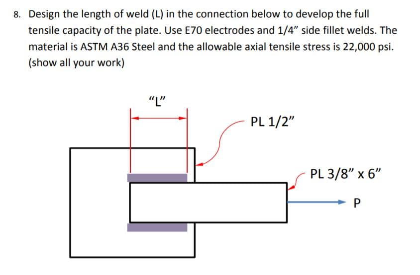
Transcribed Image Text:8. Design the length of weld (L) in the connection below to develop the full
tensile capacity of the plate. Use E70 electrodes and 1/4" side fillet welds. The
material is ASTM A36 Steel and the allowable axial tensile stress is 22,000 psi.
(show all your work)
"L"
PL 1/2"
PL 3/8" x 6"
P
Expert Solution
This question has been solved!
Explore an expertly crafted, step-by-step solution for a thorough understanding of key concepts.

This is a popular solution!

Trending now
This is a popular solution!

Step by step
Solved in 2 steps with 1 images

Knowledge Booster


Learn more about
Need a deep-dive on the concept behind this application? Look no further. Learn more about this topic, mechanical-engineering and related others by exploring similar questions and additional content below.Recommended textbooks for you
Welding: Principles and Applications (MindTap Cou…
Mechanical Engineering
ISBN:
9781305494695
Author:
Larry Jeffus
Publisher:
Cengage Learning
Welding: Principles and Applications (MindTap Cou…
Mechanical Engineering
ISBN:
9781305494695
Author:
Larry Jeffus
Publisher:
Cengage Learning