A 3-stage amplifier is to have an overall noise temperature no greater than 75°K. The overall gain of the amplifier is to be at least 40 dB. The amplifier is to be built by adding a low-noise first stage to an existing amplifier with existing characteristics as follows: Stage 2 has 20 dB power gain and 3 dB noise figure. Stage 3 has 15 dB power gain and 6 dB noise figure.
A 3-stage amplifier is to have an overall noise temperature no greater than 75°K. The overall gain of the amplifier is to be at least 40 dB. The amplifier is to be built by adding a low-noise first stage to an existing amplifier with existing characteristics as follows: Stage 2 has 20 dB power gain and 3 dB noise figure. Stage 3 has 15 dB power gain and 6 dB noise figure.

Power System Analysis and Design (MindTap Course List)
6th Edition
ISBN:9781305632134
Author:J. Duncan Glover, Thomas Overbye, Mulukutla S. Sarma
Publisher:J. Duncan Glover, Thomas Overbye, Mulukutla S. Sarma
Chapter12: Power System Controls
Section: Chapter Questions
Problem 12.3P

Related questions
Question
asap
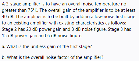
Transcribed Image Text:A 3-stage amplifier is to have an overall noise temperature no
greater than 75°K. The overall gain of the amplifier is to be at least
40 dB. The amplifier is to be built by adding a low-noise first stage
to an existing amplifier with existing characteristics as follows:
Stage 2 has 20 dB power gain and 3 dB noise figure. Stage 3 has
15 dB power gain and 6 dB noise figure.
a. What is the unitless gain of the first stage?
b. What is the overall noise factor of the amplifier?
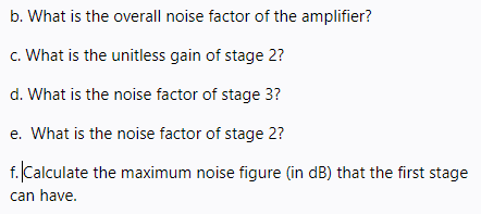
Transcribed Image Text:b. What is the overall noise factor of the amplifier?
c. What is the unitless gain of stage 2?
d. What is the noise factor of stage 3?
e. What is the noise factor of stage 2?
f. Calculate the maximum noise figure (in dB) that the first stage
can have.
Expert Solution
This question has been solved!
Explore an expertly crafted, step-by-step solution for a thorough understanding of key concepts.

Step by step
Solved in 4 steps

Recommended textbooks for you
Power System Analysis and Design (MindTap Course …
Electrical Engineering
ISBN:
9781305632134
Author:
J. Duncan Glover, Thomas Overbye, Mulukutla S. Sarma
Publisher:
Cengage Learning
Power System Analysis and Design (MindTap Course …
Electrical Engineering
ISBN:
9781305632134
Author:
J. Duncan Glover, Thomas Overbye, Mulukutla S. Sarma
Publisher:
Cengage Learning