A 555 timer configured to run as an astable mode oscillator is shown in Figure 1. If the output is needed to have 30% duty cycle, i) Determine the required value of Rị if R2 = 7kN. ii) Determine the frequency of the output. iii) Draw the charging and discharging phase of capacitor Cext and its relation with the output waveform. ASsume Vcc = 12 V.
A 555 timer configured to run as an astable mode oscillator is shown in Figure 1. If the output is needed to have 30% duty cycle, i) Determine the required value of Rị if R2 = 7kN. ii) Determine the frequency of the output. iii) Draw the charging and discharging phase of capacitor Cext and its relation with the output waveform. ASsume Vcc = 12 V.

Chapter32: Standby Power Systems
Section: Chapter Questions
Problem 7R: Briefly explain the function of a transfer switch. _____

Related questions

Question
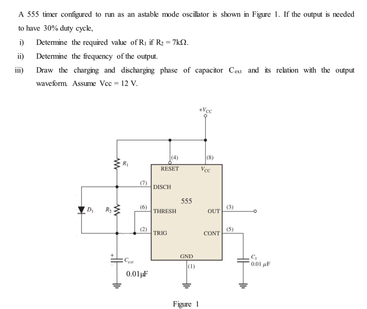
Transcribed Image Text:A 555 timer configured to run as an astable mode oscillator is shown in Figure 1. If the output is needed
to have 30% duty cycle,
i)
Determine the required value of Rị if R2 = 7kN.
ii)
Determine the frequency of the output.
iii)
Draw the charging and discharging phase of capacitor Cext and its relation with the output
waveform. ASsume Vcc = 12 V.
+Vcc
(4)
|(8)
R1
RESET
Vcc
(7)
DISCH
555
D1
R2
(6)
THRESH
(3)
OUT
(2)
TRIG
(5)
CONT
GND
:Cext
0.01 µF
(1)
0.01µF
Figure 1
Expert Solution
This question has been solved!
Explore an expertly crafted, step-by-step solution for a thorough understanding of key concepts.

This is a popular solution!

Trending now
This is a popular solution!

Step by step
Solved in 4 steps with 1 images

Knowledge Booster


Learn more about
Need a deep-dive on the concept behind this application? Look no further. Learn more about this topic, electrical-engineering and related others by exploring similar questions and additional content below.Recommended textbooks for you
EBK ELECTRICAL WIRING RESIDENTIAL
Electrical Engineering
ISBN:
9781337516549
Author:
Simmons
Publisher:
CENGAGE LEARNING - CONSIGNMENT
EBK ELECTRICAL WIRING RESIDENTIAL
Electrical Engineering
ISBN:
9781337516549
Author:
Simmons
Publisher:
CENGAGE LEARNING - CONSIGNMENT