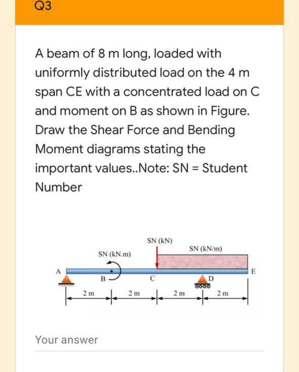
A beam of 8 m long, loaded with uniformly distributed load on the 4 m span CE with a concentrated load on C and moment on B as shown in Figure. Draw the Shear Force and Bending Moment diagrams stating the important values.Note: SN = Student %3D Number SN (kN) SN (kN/m) SN (kN.m) 609 2 m 2 m 2 m 2 m
Q: 5.41 The inverted T-beam supports three concentrated loads as shown in the fig- ure. Find the…
A: The allowable value of P for safe bending stress to be calculated. For this the maximum bending…
Q: A beam ABCDE is 5 m in length and loaded as shown in Figure Q3. Draw the S.F. and B.M. diagrams for…
A: The maximum bending stress occurs at the maximum bending moment and is given by,…
Q: Question # 1: Draw shear force and bending moment diagrams for the beam shown in Figure below.…
A:
Q: A simply supported beam AB has a length of 3 m and carries distributed load which varies in linear…
A: Given: The length of beam, L = 3 m The intensity of load at A, w1 = 1.5w The intensity of load at…
Q: A beam segment subjected to internal bending moments at sections A and B is shown along with a…
A:
Q: A simply supported beam of length 30-in diamater 2-in is supported at A and D, subject to load P at…
A:
Q: A beam ABCD with a vertical arm CE is supported as simple beam at A and D as shown in the figure. A…
A: dear student please rate me positive Stay safe stay happy!
Q: P pt 200 mm C B. 250 mm 300 mm 550 mm Act Given: Beam AB 75mmx100mm Beam CD 50mmx50mm P- BkN W =…
A:
Q: 6.. A cantilever beam is 2.5 m long, and carries a concentrated load of 380 N at its midpoint, and…
A:
Q: 1. The cantilever beam in Figure 1 is fixed at A, and is loaded with a distributed load from B to C…
A:
Q: The simple beam AB, shown below, supports a concentrated load of 22 kN and a segment of a…
A:
Q: The overhanging beam in Fig (a) below if the maximum bending stress is 20.25 kNm, find the load…
A:
Q: Figure 1a shows a simply supported beam, AB of length L = 5.6 m, with a uniform distributed load of…
A:
Q: 1. A rectangular beam120 mm wide by 400 mm deep is loaded as shown in the figure. a) Determine the…
A:
Q: a)A simply supported beam of length 6 m ,carries point load of 3 kN 4 m from the left end. Draw the…
A:
Q: A beam of 8 m long, loaded with uniformly distributed load on the 4 m span CE with a concentrated…
A: The free body diagram of the beam is as follows: Calculate the moment about point d as follows:…
Q: Draw the shear-force and bending-momentdiagrams for a cantilever beam AB carrying a uniformload of…
A:
Q: A simply supported beam AB = 10 m has a hollow rectangular cross-section with 10 cm as width, 21 cm…
A: Given data is represented as below with loading and support reactions at 'A' and 'B'.
Q: The cantilever beam with variable stiffness shown in the figure is under the effect of the M…
A:
Q: 3000 N/m (3) The beam AB shown in the figure supports a uniform load of intensity 3000 N/m acting…
A: Explanation: ◆ Before drawing SFD and BMD, we need to find the intensity of uniformly distributed…
Q: 1. The cantilever beam in Figure 1 is fixed at A, and is loaded with a distributed load from B to C…
A:
Q: Determine the shear force and bending moment at a cross section located 3m from the leading edge A.…
A: Given: To determine: The shear force and bending moment at a cross section located 3m from the…
Q: For simply supported beam below, find; Free body diagram and reaction forces Shear force value and…
A: i) Freebody Diagram and Reaction Forces: ΣMD = 0FA×7-15(1.5+2+2)-10(2)=0FA×7-102.5=0RA =14.64 KNΣFy…
Q: The figure below shows a hollow circular beam with an outside diameter of 150 mm and a wall…
A:
Q: Consider the beam shown in the figure. Suppose that the distributed load w = 650 lb/ft . Follow the…
A: Solution ; As the loading is symmetric, so reaction at the support will be equal :…
Q: Draw the complete shearing force and bending moment diagram for the beam shown in figure. Show…
A:
Q: Uniformly distributed load on a simple support beam with a length of 6 meters Maximum that occurs on…
A: Given data: The length of the beam is l = 6 m. The bending stress of the beam is σ = 337.5 MPa. The…
Q: Q: For the loaded simply supported beam shown in figure below, if the allowable bending stress is…
A:
Q: The figure below shows a hollow circular beam with an outside diameter of 100 mm and a wall…
A: NOTE: According to Bartleyby's policy we shall answer only three sub-parts of a question so kindly…
Q: Write shear and moment equations for the beam loaded as shown in figure below. Also, draw shear and…
A:
Q: simply supported beam of length 3 m, is subjected to an Uniformly distributed load of 28 kN/m for…
A: Note: As per the Bartleby guidelines, only three parts of a question can be answered at a time.…
Q: Figure 6 shows a beam of length 8 m, simply supported at each end, and loaded with a point load of…
A: Consider upward force & CW moment as (+)ve and downward force & CCW moment as (-)ve. Net…
Q: А C 2а
A:
Q: Draw the shear and moment diagram of the cantilever beam shown below. For this part, please show the…
A: Consider upward force & CW moment as (+)ve and downward force & CCW moment as (-)ve. Let…
Q: The overhanging beam ABC in figure carries a concentrated load and a uniformly distributed load.…
A:
Q: A simply supported beam AB has a length of 3 m and carries distributed load which varies in linear…
A: Simply supported beam Simply supported beam is the beam in which beam is simply supported at both…
Q: 3. For the structure carrying a uniform load of 4 kN/ m, compute the internal axial force, shear…
A: First draw the free body diagram of the horizontal beam, Then draw the free body diagram of the…
Q: Q1: For the square beam shown below, the cross section area is 40 m, a) Find the shear force and…
A: Consider the square beam, In support A the reaction force is RA consider and in support C the…
Q: An electrical worker stands in the bucket that hangs from a pin at end D of the boom of the cherry…
A: The weight of worker and bucket together is 300lb Therefore the Free body diagram is
Q: Ql: A beam with overhang is supported and loaded as shown in Figure. Draw the shear force and the…
A: The free-body diagram of the beam is shown below. Here, HA, VA, and VD are the reactions at the…
Q: An indeterminate beam carries a distributed load and concentrated load as shown in the figure. Solve…
A: Solution: Location A, Moment Reaction =-544.8973 (kN-m) Location C, Moment Reaction =…
Q: Q#4: A continuous beam AB, 6 m long having three supports is loaded as shown in Fig.2. Construct the…
A: In this solution you may find the difficulty as the value of x varies from 0 to 1.5 in each portion…
Q: Example A beam of I - section 400 mm deep and 180 mm wide has flange of thickness 20 mm each and web…
A: we will first draw the SFD of the beam and find out max shear stress. then we will find out max…
Q: Draw diagram shear force and bending moment to cantilever beam which shown in the figure. W=5 KN/m…
A: The Shear Force Diagram (SFD) and Bending Moment Diagram (BMD) are very important tools to analyze a…
Q: A steel beam ABC carries a concentrated load of P (kN) at B and C, as shown in Figure Q3(a). The…
A: Drawing the free body diagram as shown below, ∑Fy=0VA+VB=2P∑MA=0 P×10+P×15=VB×10VB=2.5P, VA=-0.5P…
Q: A simply supported beam AB = 10 m has a hollow rectangular cross-section with 17 cm as width, 28 cm…
A:
Q: For structural member steel beam with an overhang as shown below, determine a) the support…
A:
Q: 1- The below cantilever beam AB of length L= 3m carries a uniformly distributed load of intensity w…
A:
Q: A horizontal beam AE, 12 m long and it carries a uniformly distributed load of 3.8 kN/m over the…
A:
Q: Draw the Shear Force and Bending Moment diagrams stating the important values
A:
Step by step
Solved in 5 steps with 4 images
- The hollow box beam shown in the figure is subjected to a bending moment M of such magnitude that the flanges yield but the webs remain linearly elastic. (a) Calculate the magnitude of the moment M if the dimensions of the cross section are A = 15 in., A] = 12.75 in., h = 9 in., and ey =7.5 in. Also, the yield stress is eY = 33 ksi. (b) What percent of the moment M is produced by the elastic core?A two-axle carriage that is part of an over head traveling crane in a testing laboratory moves slowly across a simple beam AB (sec figure). The load transmitted to the beam from the front axle is 2200 lb and from the rear axle is 3800 lb. The weight of the beam itself may be disregarded. Determine the minimum required section modulus S for the beam if the allowable bending stress is 17,0 ksi, the length of the beam is 18 ft, and the wheelbase of the carriage is 5 ft. Select the most economical I-beam (S shape) from Table F-2(a), Appendix F.A rectangular beam with semicircular notches, as shown in part b of the figure, has dimensions h = 0,88 in. and h1 = 0.80 in. The maximum allowable bending stress in the metal beam is emax = 60 ksi, and the bending moment is M = 600 lb-in. Determine the minimum permissible width bminof the beam.
- The beam ABC shown in the figure is simply supported at A and B and has an overhang from B to C. The loads consist of a horizontal force P1= 4,0 kN acting at the end of a vertical arm and a vertical force P2= 8.0 kN acting at the end of the overhang, Determine the shear force Fand bending moment M at a cross section located 3,0 m from the left-hand support. Note: Disregard the widths of the beam and vertical arm and use centerline dimensions when making calculations, Find the value of load A that results in V = 0 at a cross section located 2.0 m from the left-hand support. If P2= 8.0 kN, find the value of load P1that results in M = 0 at a cross section located 2,0 m from the left-hand support.A hollow box beam with height h = 16 in,, width h = 8 in,, and constant wall thickness r = 0.75 LiL is shown in the figure. The beam is constructed of steel with yield stress ty = 32 ksi. Determine the yield moment My, plastic moment A/p, and shape factor.A rectangular beam with semicircular notches, as shown in part b of the figure, has dimensions h = 120 mm and h1= 100 mm. The maximum allowable bending stress in the plastic beam is emix = 6 M Pa, and the bending moment is M = 150 N · m. Determine the minimum permissible width bminof the beam.
- A heavy object of weight W is dropped onto the midpoint of a simple beam AB from a height h (see figure). Obtain a formula for the maximum bending stress ^ma* due to tne filing weight in terms of h, st, and 5st, where it is the maximum bending stress and Sstis the deflection at the midpoint when the weight W acts on the beam as a statically applied load. Plot a graph of the ratio o"max/ö"it (that is, the ratio of the dynamic stress to the static stress) versus the ratio iifS^r(Let h/S^ vary from 0 to 10.)Two identical, simply supported beams AB and CD are placed so that they cross each other at their midpoints (sec figure). Before the uniform load is applied, the beams just touch each other at the crossing point. Determine the maximum bending moments (mab)max* and (MCD)max beams AB and CD, respectively, due to the uniform load if the intensity of the load is q = 6.4 kN/m and the length of each beam is L = 4 m.A C 200 x 17.1 channel section has an angle with equal legs attached as shown; the angle serves as a lintel beam. The combined steel section is subjected to a bending moment M having its vector directed along the z axis, as shown in the figure. The cent roi d C of the combined section is located at distances xtand ycfrom the centroid (C1) of the channel alone. Principal axes yl and yvare also shown in the figure and properties Ix1,Iy1and 0pare given. Find the orientation of the neutral axis and calculate the maximum tensile stress exand maximum compressive stress if the angle is an L 76 x 76 x 6.4 section and M = 3.5 kN - m. Use the following properties for principal axes for the combined section:/^, = 18.49 X 10⁶ nrai4,/;| = 1.602 X 106 mm4, ep= 7.448*(CW),_r£ = 10.70 mm,andvf= 24.07 mm.
- A beam supporting a uniform load of intensity q throughout its length rests on pistons at points A, C and B (sec figure). The cylinders are filled with oil and are connected by a tube so that the oil pressure on each piston is the same. The pistons at A and B have diameter d1and the piston at C has diameter D2. (a) Determine the ratio of d2to d1so that the largest bending moment in the beam is as small as possible. Under these optimum conditions, what is the largest bending moment Mmaxin the beam? What is the difference in elevation between point C and the end supports?The cross section of a rectangular beam having a width b and height h is shown in part a of the figure. For reasons unknown to the beam designer, it is planned to add structural projections of width b/9 and height d/9 the top and bottom of the beam (see part b of the figure). For what values of d is the bending-moment capacity of the beam increased? For what values is it decreased?The cross section of a sand wie h beam consisting of aluminum alloy faces and a foam core is shown in the figure. The width b of the beam is 8.0 in, the thickness I of the faces is 0.25 in., and the height hcof the core is 5.5 in. (total height h = 6.0 in). The moduli of elasticity are 10.5 × 10⁶ psi for the aluminum faces and 12.000 psi for the foam core. A bending moment M = 40 kip-in. acts about the z axis. Determine the maximum stresses in the faces and the core using (a) the general theory for composite beams and (b) the approximate theory for sandwich beams.