Ql: A beam with overhang is supported and loaded as shown in Figure. Draw the shear force and the bending moment diagrams, showing clearly the position and maximum B.M in the beam. 20 KN 2m 2 m 3m
Ql: A beam with overhang is supported and loaded as shown in Figure. Draw the shear force and the bending moment diagrams, showing clearly the position and maximum B.M in the beam. 20 KN 2m 2 m 3m

Mechanics of Materials (MindTap Course List)
9th Edition
ISBN:9781337093347
Author:Barry J. Goodno, James M. Gere
Publisher:Barry J. Goodno, James M. Gere
Chapter10: Statically Indeterminate Beams
Section: Chapter Questions
Problem 10.4.15P: Determine the fixed-end moments (MAand MB) and fixed-end forces (R4and Rs) for a beam of length L...

Related questions
Question
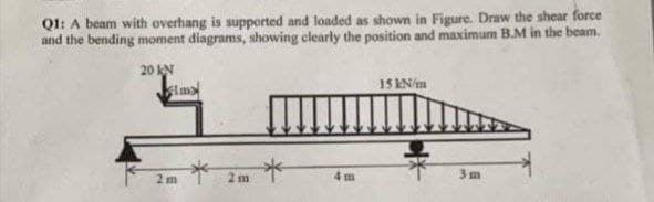
Transcribed Image Text:Ql: A beam with overhang is supported and loaded as shown in Figure. Draw the shear force
and the bending moment diagrams, showing clearly the position and maximum B.M in the beam.
20 KN
stma
4 m
3m
Expert Solution
This question has been solved!
Explore an expertly crafted, step-by-step solution for a thorough understanding of key concepts.

Step by step
Solved in 4 steps with 3 images

Knowledge Booster


Learn more about
Need a deep-dive on the concept behind this application? Look no further. Learn more about this topic, mechanical-engineering and related others by exploring similar questions and additional content below.Recommended textbooks for you
Mechanics of Materials (MindTap Course List)
Mechanical Engineering
ISBN:
9781337093347
Author:
Barry J. Goodno, James M. Gere
Publisher:
Cengage Learning
Mechanics of Materials (MindTap Course List)
Mechanical Engineering
ISBN:
9781337093347
Author:
Barry J. Goodno, James M. Gere
Publisher:
Cengage Learning