
Mechanics of Materials (MindTap Course List)
9th Edition
ISBN: 9781337093347
Author: Barry J. Goodno, James M. Gere
Publisher: Cengage Learning
expand_more
expand_more
format_list_bulleted
Videos
Textbook Question
Chapter 4, Problem 4.3.6P
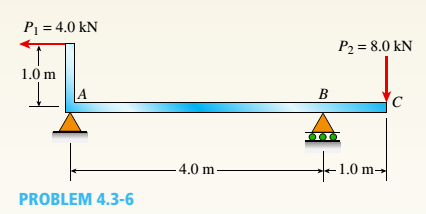
The beam ABC shown in the figure is simply supported at A and B and has an overhang from B to C. The loads consist of a horizontal force P1= 4,0 kN acting at the end of a vertical arm and a vertical force P2= 8.0 kN acting at the end of the overhang,
- Determine the shear force Fand bending moment M at a cross section located 3,0 m from the left-hand support. Note: Disregard the widths of the beam and vertical arm and use centerline dimensions when making calculations,
- Find the value of load A that results in V = 0 at a cross section located 2.0 m from the left-hand support.
- If P2= 8.0 kN, find the value of load P1that results in M = 0 at a cross section located 2,0 m from the left-hand support.
Expert Solution & Answer

Trending nowThis is a popular solution!

Chapter 4 Solutions
Mechanics of Materials (MindTap Course List)
Ch. 4 - Calculate the shear force V and bending moment...Ch. 4 - Determine the shear force V and bending moment M...Ch. 4 - Determine the shear force V and bending moment M...Ch. 4 - Calculate the shear force V and bending moment M...Ch. 4 - Consider the beam with an overhang shown in the...Ch. 4 - The beam ABC shown in the figure is simply...Ch. 4 - The beam ABCD shown in the figure has overhangs at...Ch. 4 - At a full d raw, an archer applies a pull of 130 N...Ch. 4 - A curved bar ABC is subjected to loads in the form...Ch. 4 - Under cruising conditions, the distributed load...
Ch. 4 - A beam ABCD with a vertical arm CE is supported as...Ch. 4 - A simply supported beam AB supports a trapezoid...Ch. 4 - Beam ABCD represents a reinforced-concrete...Ch. 4 - Find shear (V) and moment (M) at x = 3L/4 for the...Ch. 4 - Find expressions for shear force V and moment M at...Ch. 4 - Find expressions for shear force V and moment Mat...Ch. 4 - Find expressions for shear force V and moment Mat...Ch. 4 - Find expressions for shear force V and moment M at...Ch. 4 - Find expressions for shear force V and moment M at...Ch. 4 - Find expressions for shear force V and moment M at...Ch. 4 - A cable with force P is attached to a frame at A...Ch. 4 - Find expressions for shear force V and moment M at...Ch. 4 - A cable with force P is attached to a frame at D...Ch. 4 - Frame ABCD carries two concentrated loads (2P at T...Ch. 4 - Frame ABC has a moment release just left of joint...Ch. 4 - The simply supported beam ABCD is loaded by a...Ch. 4 - The centrifuge shown in the figure rotates in a...Ch. 4 - Draw the shear-Force and bending-moment diagrams...Ch. 4 - A simple beam AB is subjected to a counter...Ch. 4 - Draw the shear-force and bending-moment diagrams...Ch. 4 - The cantilever beam AB shown in the figure is...Ch. 4 - Cantilever beam AB carries an upward uniform load...Ch. 4 - The simple beam AB shown in the figure is...Ch. 4 - A simple beam AB subjected to couples M1and 3M2...Ch. 4 - A simply supported beam ABC is loaded by a...Ch. 4 - A simply supported beam ABC is loaded at the end...Ch. 4 - A beam ABC is simply supported at A and B and has...Ch. 4 - Beam ABCD is simply supported at B and C and has...Ch. 4 - Draw the shear-force and bending-moment diagrams...Ch. 4 - The simple beam AB supports a triangular load of...Ch. 4 - The beam AB shown in the figure supports a uniform...Ch. 4 - A cantilever beam AB supports a couple and a...Ch. 4 - The cantilever beam A B shown in the figure is...Ch. 4 - Beam ABC has simple supports at .A and B. an...Ch. 4 - Beam ABC with an overhang at one end supports a...Ch. 4 - Consider the two beams shown in the figures. Which...Ch. 4 - The three beams in the figure have the same...Ch. 4 - The beam ABC shown in the figure is simply...Ch. 4 - A simple beam AB is loaded by two segments of...Ch. 4 - Two beams (see figure) are loaded the same and...Ch. 4 - The beam A BCD shown in the figure has overhangs...Ch. 4 - A beam ABCD with a vertical arm CE is supported as...Ch. 4 - Beams ABC and CD are supported at A,C, and D and...Ch. 4 - The simple beam ACE shown in the figure is...Ch. 4 - A beam with simple supports is subjected to a...Ch. 4 - A beam of length L is designed to support a...Ch. 4 - The compound beam ABCDE shown in the figure...Ch. 4 - Draw the shear-force and bending-moment diagrams...Ch. 4 - The shear-force diagram for a simple beam is shown...Ch. 4 - The shear-force diagram for a beam is shown in the...Ch. 4 - A compound beam (see figure) has an internal...Ch. 4 - A compound beam (see figure) has an shear release...Ch. 4 - A simple beam AB supports two connected wheel...Ch. 4 - The inclined beam represents a ladder with the...Ch. 4 - Beam ABC is supported by a tie rod CD as shown....Ch. 4 - A plane frame (see figure) consists of column AB...Ch. 4 - The plane frame shown in the figure is part of an...
Knowledge Booster


Learn more about
Need a deep-dive on the concept behind this application? Look no further. Learn more about this topic, mechanical-engineering and related others by exploring similar questions and additional content below.Similar questions
- A wood beam reinforced by an aluminum channel section is shown in the figure. The beam has a cross section of dimensions 150 mm x 250 mm, and the channel has a uniform thickness of 6.5 mm. If the allowable stresses in the wood and aluminum are 8 M Pa and 38 M Pa, respectively, and if their moduli of elasticity are in the ratio 1 to 6, what is the maximum allowable bending moment for the beam?arrow_forwardA simple beam of span length 3.2 m carries a uniform load of intensity 48 kN/m, The cross section of the beam is a hollow box with wood flanges and steel side plates, as shown in the figure. The wood flanges are 75 mm x 100 mm in cross section, and the steel plates are 300 mm deep. What is the required thickness t of the steel plates if the allowable stresses are 120 M Pa for the steel and 6,5 M Pa for the wood? (Assume that the moduli of elasticity for the steel and wood are 210 GPa and 10 GPa, respectively, and disregard the weight of the beam.)arrow_forwardConsider the preceding problem if the beam has width h = 15 mm, the aluminum strips have thickness t = 3 mm, the plastic segments have heights d = 40 mm and 3 tf = 120 mm, and the total height of the beam is h = 212 mm. Also, the moduli of elasticity are EA= 75 GPa and Ep=3 GPa, respectively. Determine the maximum stresses o., and o\, in the aluminum and plastic, respectively, due to a bending moment of 1.0 kN - m.arrow_forward
- Consider the beam with an overhang shown in the figure. Determine the shear force V and bending moment M at a cross section located 18 ft from the left-hand end A. Find the required magnitude of load intensity q acting on the right half of member SC that will result in a zero shear force on the cross section IS ft from A.arrow_forwardA vertical pole of solid, circular cross section is twisted by horizontal forces P = 5kN acting at the ends of a rigid horizontal arm AB (see figure part a). The distance from the outside of the pole to the line of action of each force is c = 125 mm (sec figure part b) and the pole height L = 350 mm. (a) If the allowable shear stress in the pole is 30 MPa, what is the minimum required diameter dminof the pole? (b) What is the torsional stiffness of the pole (kN · m/rad)? Assume that G = 28 GPa. (c) If two translation al springs, each with stiffness k =2550 kN/m, are added at 2c/5 from A and B (see figure part c), repeat part (a) to find dmin. Hint: Consider the pole and pair of springs as "springs in parallel."arrow_forwardA thin-walled steel tube of rectangular cross section (see figure) has centerline dimensions b = 150 mm and h = 100 mm. The wall thickness t is constant and equal to 6.0 mm. Determine the shear stress in the tube due to a torque T = 1650 N · m. Determine the angle of twist (in degrees) if the length L of the tube is 1.2 m and the shear modulus G is 75 GPa.arrow_forward
- The cross section of a composite beam made of aluminum and steel is shown in the figure. The moduli of elasticity are TA= 75 GPa and Es= 200 GPa. Under the action of a bending moment that produces a maximum stress of 50 M Pa in the aluminum, what is the maximum stress xs in the steel? If the height of the beam remains at 120 mm and allowable stresses in steel and aluminum are defined as 94 M Pa and 40 M Pa, respectively, what heights h and h. arc required for aluminum and steel, respectively, so that both steel and aluminum reach their allowable stress values under the maximum moment?arrow_forwardA simple beam with a rectangular cross section (width, 3,5 inL; height, 12 in,) carries a trapczoi-dally distributed load of 1400 lb/ft at A and 1000 lb/ft at B on a span of 14 ft (sec figure). Find the principal stresses 2 and the maximum shear stress r__ at a cross section 2 ft from the left-hand support at each of the locations: (a) the neutral axis, (b) 2 in. above the neutral axis, and (c) the top of the beam. (Disregard the direct compressive stresses produced by the uniform load bearing against the top of the beam.)arrow_forwardA reinforced concrete slab (see figure) is reinforced with 13-mm bars spaced 160 mm apart at d = 105 mm from the top of the slab. The modulus of elasticity for the concrete is Ec= 25 GPa, while that of the steel is £s = 200 G Pa. Assume that allowable stresses for concrete and steel arecrac = 9.2 MPa and us = 135 MPa. l()5 mm Find the maximum permissible positive bending moment for a l-m wide strip of the slab. What is the required area of steel reinforcement, A^ if a balanced condition must be achieved? What is the allowable positive bending moment? (Recall that in a balanced design, both steel and concrete reach allowable stress values simultaneously under the design moment.)arrow_forward
- The composite beam shown in the figure is simply supported and carries a total uniform load of 40 kN/m on a span length of 4.0 m. The beam is built of a southern pine wood member having cross-sectional dimensions of 150 mm × 250 mm and two brass plates of cross-sectional dimensions 30 mm × 150 mm. Determine the maximum stresses (7b and ctwin the brass and wood, respectively, if the moduli of elasticity are EB= % GPa and Ew= 14 GPa. (Disregard the weight of the beam.) Find the required thickness of the brass plates so that the plate and wood reach their allowable stress values of Eb= 70 MPa and t Ew= 8.5 MPa simultaneously under the maximum moment. What is the maximum moment?arrow_forwardTwo pipe columns (AB, FC) are pin-connected to a rigid beam (BCD), as shown in the figure. Each pipe column has a modulus of E, but heights (L1or L2) and outer diameters (d1or different for each column. Assume the inner diameter of each column is 3/4 of outer diameter. Uniformly distributed downward load q = 2PIL is applied over a distance of 3L/4 along BC, and concentrated load PIA is applied downward at D. (a) Derive a formula for the displacementarrow_forwardA W 12 x 50 steel wide-flange beam and a segment of a 4-inch thick concrete slab (see figure) jointly resist a positive bending moment of 95 kip-ft. The beam and slab are joined by shear connectors that are welded to the steel beam. (These connectors resist the horizontal shear at the contact surface.) The moduli of elasticity of the steel and the concrete are in the ratio 12 to 1. Determine the maximum stresses r1 and xtin the steel and concrete, respectively. Note: See Table F-l(a) of Appendix F for the dimensions and properties of the steel beam.arrow_forward
arrow_back_ios
SEE MORE QUESTIONS
arrow_forward_ios
Recommended textbooks for you
 Mechanics of Materials (MindTap Course List)Mechanical EngineeringISBN:9781337093347Author:Barry J. Goodno, James M. GerePublisher:Cengage Learning
Mechanics of Materials (MindTap Course List)
Mechanical Engineering
ISBN:9781337093347
Author:Barry J. Goodno, James M. Gere
Publisher:Cengage Learning
Everything About TRANSVERSE SHEAR in 10 Minutes!! - Mechanics of Materials; Author: Less Boring Lectures;https://www.youtube.com/watch?v=4x0E9yvzfCM;License: Standard Youtube License