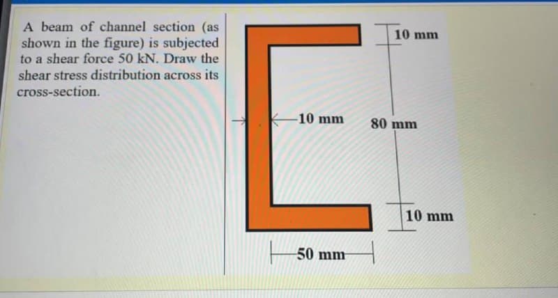
A beam of channel section (as shown in the figure) is subjected to a shear force 50 kN. Draw the shear stress distribution across its 10 mm cross-section. -10 mm 80 mm 10 mm
Q: A hollow steel box beam has the rectangularcross section shown in the figure. Determinethe maximum…
A: Given Allowable shear stress = 36 MPa To find Allowable shear force
Q: A wood beam reinforced by an aluminumchannel section is shown in the figure. The beam hasa cross…
A: According to the problem, n=EaEw =6 Here, n is the ratio of Young's Modulus, Ea is the Young's…
Q: Given an overhanging beam loaded as shown in the figure. 40 KN 30 KN/m 10 KN-m 3m 2 m 2 m 1.1.…
A: (1.1) Draw the free-body diagram.
Q: The beam cross section shown in the figure below is subjected to a shear force V = 250 kN.…
A:
Q: The vertical shear force acting in a beam with the cross section shown in the figure is 20 kips.…
A:
Q: H.W Draw shear force and bending moment diagrams for a cantilever beam as shown in Figure? I kN/m -…
A: Shear force diagram represents shear force at every section of the beam.. Shear force at any…
Q: In the simple beam given in the figure, Find the maximum slope and depression using the values…
A: When any beam is subjected to a load, it deflects, and the neutral axis becomes a curved line which…
Q: The beam ABCD with a rectangular cross section carries the loading shown in the figure. Determine…
A:
Q: H.W: Find the values of the shear stress at point A, 3, and C in the beam Cross- Sedion shown in the…
A: A circular hollow cross-section shaft is subjected to a shear force of 100 kN. Points A, B, and C is…
Q: A thin-walled closed section beam of constant wall thickness t has the cross-section shown in…
A: Given data as per question The thickness of the thin-walled closed section beam =t
Q: The beam, which consists of three parts with a vertical cross section as shown in the figure, will…
A: As per the guidelines, I can solve only part (a). For part (b), please re-post in a separate post.…
Q: A circular beam carries a concentrated and a distributed load as shown in the figure. Determine the…
A: An overhanging beam is one in which the terminal portion of the beam extends beyond the support.…
Q: The distributed load on the T-section beam in the figure is w = 100 kN/m. The tensile stress that…
A: Bending stress in beams When external load acts on beam shear force and bending moment are set up at…
Q: The beam shown in the figure is made of Wood that has an Allowable Shear Stress of 200 psi;…
A:
Q: A beam has the singly symmetrical thin-walled cross section shown in the figure. The thickness t of…
A: FBD for the given diagram: The share center S lies on the horizontal axis of symmetry , Gz.Applying…
Q: 3. A built-up beam of box section as shown in Figure 3 is simply supported over a span of 3 m and…
A:
Q: Asimply supported wood beam that is 4,5 m long carries a 32 kN concentrated load at 8. The…
A:
Q: 2 kN 4 kN For the cantilever beam shown in figure. Determine the shear stress at point B on the web…
A: The free body diagram of the beam is as follows: Calculate the shear force R for the section a-a as…
Q: The maximum bending stress at distance 0.5 m from the built-in right hand end in the structural beam…
A:
Q: Determine the flexural stress and shear stress of a rectangular beam loaded as shown in the figure…
A: Given data: For hallow rectangle the loading diagram is given below
Q: Consider the T-beam as shown in the figure a) Determine the maximum shear stress at the critical…
A: Given figure
Q: The cross-sectional beam shown in the figure is subject to a maximum shear stress of 35 ksi, due to…
A:
Q: Cross section of a beam is shown in Figure 3. If a shear force V=100 kN is applied to the beam, find…
A:
Q: Find the maximum transverse shear stress in the thin walled box beam shown in the figure below. This…
A:
Q: In the simple beam given in the figure, Find the maximum slope and depression using the values.…
A: When any beam is subjected to a load, it deflects, and the neutral axis becomes a curved line which…
Q: The beam given in the figure below is subjected to the uniform distributed load of w=50 kN/m. (a)…
A:
Q: A steel wide-flange beam has the dimensions as shown in the figure below. If it is subjected to…
A: According to the given information we have shear force of v = 86 Kn firstly for the moment of…
Q: Since the bending safety stress Bem = 10 MPa and shear safety stress Bem = 600 kPa of the…
A: Given, Safe bending stress ,σb =10 MPa Safe shear stress , ζs=600 KPa
Q: 120 KN 100 mm H 400 mm B 22m 150 mm Find the shear stress at point H on the beam. The wall thickness…
A:
Q: For the beam shown in the figure, find the shear stress at a point 25 mm above the bottom of the…
A: Given, A simply supported beam with point load , P =14 KN Moment of inertia of the cross section ,…
Q: The maximum bending stress at distance 0.5 m from the built-in right hand end in the structural beam…
A:
Q: A simply supported beam of length 6 m carries a load of 4 kN/m along its span. The beam cross…
A: ∑MA=0 6RB=4×6×3RB=12 KN shear force is maximum at supports Vmax=RB=12 KN I=2.36×109 mm4 Shear force…
Q: In the simple beam given in the figure, Find the maximum slope and depression using the values.…
A: The bending moment is a reaction in a structural element that is subjected to an external force or…
Q: Rectangular cross-section and width given the loading state in the figure Bending safety stress of…
A:
Q: The beam given in the figure below is subjected to the uniform distributed load of w350 kN/m. (a)…
A:
Q: H.W Draw shear force and bending moment diagrams for a cantilever beam as shown in Figure? I KN/m-…
A:
Q: A beam has the singly symmetrical thin-walled cross section shown in the figure. The thickness t of…
A: FBD for the given figure:
Q: A cantilever beam of length 2 m carries the point loads as shown in Fig 2. Draw the shear force and…
A:
Q: 5.8-6) A cantilever beam of length L = 2 m sup- ports a load P = 8.0 kN (see figure). The beam is…
A:
Q: Rectangular cross-section and width given the loading state in the figure Bending safety stress of…
A:
Q: Rectangular section and width given in the figure The bending safety stress of the beam with b = 150…
A:
Q: Q1: The thin-walled single cell beam shown in Fig.1 has been idealized into a combination of direct…
A:
Q: A (14-ft long) simply supported timber beam subjected to shear force of (3-kip) as shown in Figure.…
A: Given data as per question Shear force on beam =3 kip Length of the beam =14 ft Moment of inertia…
Q: The figure shows the cross-section of a beam that is composed of a wide-flanged structural profile,…
A: Given data Vertical shear force (F)=25 kN No of screw =4No of steel plate =2Diameter of screw…
Q: for the loaded beam as shown in the figure on the m-m section a) the greatest value of shear stress…
A:
Q: 2. The cantilever beam shown in the figure below is subjected to loads P, = 3 kips and P, = 8.5…
A:
Q: 6 kN/m Since the bending safety stress *em = 10 MPa, shear safety stress em = 600 kPa of the…
A: Draw a diagram for the beam. Here, RA and RC are the support reactions as shown in the figure.…
Q: beam section h is at least how much is the height of the beam section in order not to exceed the…
A:
Trending now
This is a popular solution!
Step by step
Solved in 2 steps with 1 images
- A hollow steel box beam has the rectangular cross section shown in the figure. Determine the maximum allowable shear force K that may act on the beam if the allowable shear stress is 36 MPa. cA beam of wide-flange shape, W 8 x 28, has the cross section shown in the figure. The dimensions are b = 6.54 in., h = 8.06 in., fw = 0.285 in., and tf = 0.465 in.. The loads on the beam produce a shear force V = 7.5 kips at the cross section under consideration. Use center line dimensions to calculate the maximum shear stress raiaxin the web of the beam. Use the more exact analysis of Section 5,10 in Chapter 5 to calculate the maximum shear stress in the web of the beam and compare it with the stress obtained in part .A hollow box beam with height h = 16 in,, width h = 8 in,, and constant wall thickness r = 0.75 LiL is shown in the figure. The beam is constructed of steel with yield stress ty = 32 ksi. Determine the yield moment My, plastic moment A/p, and shape factor.
- The cross section of a rectangular beam having a width b and height h is shown in part a of the figure. For reasons unknown to the beam designer, it is planned to add structural projections of width b/9 and height d/9 the top and bottom of the beam (see part b of the figure). For what values of d is the bending-moment capacity of the beam increased? For what values is it decreased?A hollow aluminum box beam has the square cross section shown in the figure. Calculate the maximum and minimum shear stresses tmaxand tminin the webs of the beam due to a shear force V = 28 k.The beams shown in the figure are subjected to bending moments M = 2100 lb-in. Each beam has a rectangular cross section with height h = 1.5 in. and width b = 0,375 in, (perpendicular to the plane of the figure). For the beam with a hole at m id height, determine the maximum stresses for hole diameters d = 0.25,0.50, 0.75, and 1,00 in. For the beam with two identical notches (inside height /j| = 1.25 in.), determine the maximum stresses for notch radii R = 0.05, 0.10, 0.15 and 0.20 in.
- The T-beam shown in the figure has cross-sectional dimensions: b = 210 mm, t = 16 mm, h = 300 mm, and A, = 280 mm. The beam is subjected to a shear force V = 68 kN. Determine the maximum shear stress tntijlin the web of the beam.A W 12 x 50 steel wide-flange beam and a segment of a 4-inch thick concrete slab (see figure) jointly resist a positive bending moment of 95 kip-ft. The beam and slab are joined by shear connectors that are welded to the steel beam. (These connectors resist the horizontal shear at the contact surface.) The moduli of elasticity of the steel and the concrete are in the ratio 12 to 1. Determine the maximum stresses r1 and xtin the steel and concrete, respectively. Note: See Table F-l(a) of Appendix F for the dimensions and properties of the steel beam.A simple beam with a W 10 x 30 wide-flange cross section supports a uniform load of intensity q = 3.0 kips/ft on a span of length L = 12 ft (sec figure). The dimensions of the cross section are q = 10.5 in., b = 5.81 in., t1= 0.510 in., and fw = 0.300 in. Calculate the maximum shear stress tjuly on cross section A—A located at distance d = 2.5 ft from the end of the beam. Calculate the shear stress rat point Bon the cross section. Point B is located at a distance a = 1.5 in. from the edge of the lower flange.
- The hollow box beam shown in the figure is subjected to a bending moment M of such magnitude that the flanges yield but the webs remain linearly elastic. (a) Calculate the magnitude of the moment M if the dimensions of the cross section are A = 15 in., A] = 12.75 in., h = 9 in., and ey =7.5 in. Also, the yield stress is eY = 33 ksi. (b) What percent of the moment M is produced by the elastic core?The beams shown in the figure are subjected to bending moments M = 250 N · m. Each beam has a rectangular cross section with height f1= 44 mm and width d = 10 mm (perpendicular to the plane of the figure). For the beam with a hole at m id height, determine the maximum stresses for hole diameters d = 10, 16,22, and 28 mm. For the beam with two identical notches (inside height d= 40 mm), determine the maximum stresses for notch radii R = 2,4, 6, and 8 mm.The cross section of an unbalanced wide-flange beam is shown in the figure. Derive the following formula for the distance /h from the centerline of one flange to the shear center S: h1t2b23ht1b13+t2b23 Also, check the formula for the special cases of a T-beam (b2= t2=0) and a balanced wide-flange beam (t2= ttand b2= ty).