A cantilever beam is loaded as shown in the figure. What is the bending moment in the beam at 0.5 m distance from the clamp support A? |4.5 kN 2.5 kN/m B 2.0m2.0m- 4.0m- -35.25 kN.m -14.5 kN.m -40 kN.m O -61.75 kN.m
A cantilever beam is loaded as shown in the figure. What is the bending moment in the beam at 0.5 m distance from the clamp support A? |4.5 kN 2.5 kN/m B 2.0m2.0m- 4.0m- -35.25 kN.m -14.5 kN.m -40 kN.m O -61.75 kN.m

Mechanics of Materials (MindTap Course List)
9th Edition
ISBN:9781337093347
Author:Barry J. Goodno, James M. Gere
Publisher:Barry J. Goodno, James M. Gere
Chapter9: Deflections Of Beams
Section: Chapter Questions
Problem 9.3.5P: What is the span length L of a uniformly loaded, simple beam of wide-flange cross section (see...

Related questions
Question
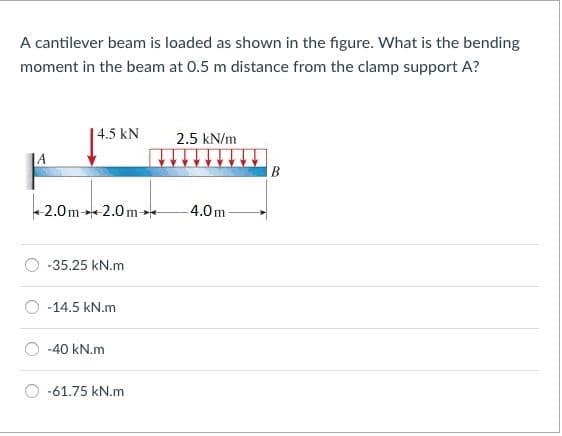
Transcribed Image Text:A cantilever beam is loaded as shown in the figure. What is the bending
moment in the beam at 0.5 m distance from the clamp support A?
| 4.5 kN
2.5 kN/m
JA
В
+2.0m→2.0me
4.0m-
-35.25 kN.m
-14.5 kN.m
-40 kN.m
-61.75 kN.m
Expert Solution
This question has been solved!
Explore an expertly crafted, step-by-step solution for a thorough understanding of key concepts.

Step by step
Solved in 2 steps with 2 images

Knowledge Booster


Learn more about
Need a deep-dive on the concept behind this application? Look no further. Learn more about this topic, mechanical-engineering and related others by exploring similar questions and additional content below.Recommended textbooks for you
Mechanics of Materials (MindTap Course List)
Mechanical Engineering
ISBN:
9781337093347
Author:
Barry J. Goodno, James M. Gere
Publisher:
Cengage Learning
Mechanics of Materials (MindTap Course List)
Mechanical Engineering
ISBN:
9781337093347
Author:
Barry J. Goodno, James M. Gere
Publisher:
Cengage Learning