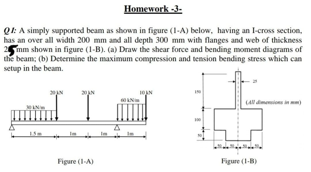
Q1: A simply supported beam as shown in figure (1-A) below, having an I-cross section, has an over all width 200 mm and all depth 300 mm with flanges and web of thickness 2 mm shown in figure (1-B). (a) Draw the shear force and bending moment diagrams of the beam; (b) Determine the maximum compression and tension bending stress which can setup in the beam.
Q1: A simply supported beam as shown in figure (1-A) below, having an I-cross section, has an over all width 200 mm and all depth 300 mm with flanges and web of thickness 2 mm shown in figure (1-B). (a) Draw the shear force and bending moment diagrams of the beam; (b) Determine the maximum compression and tension bending stress which can setup in the beam.

Mechanics of Materials (MindTap Course List)
9th Edition
ISBN:9781337093347
Author:Barry J. Goodno, James M. Gere
Publisher:Barry J. Goodno, James M. Gere
Chapter5: Stresses In Beams (basic Topics)
Section: Chapter Questions
Problem 5.10.12P: The T-beam shown in the figure has cross-sectional dimensions: b = 210 mm, t = 16 mm, h = 300 mm,...

Related questions
Question
Transcribed Image Text:Homework -3-
Q1: A simply supported beam as shown in figure (1-A) below, having an I-cross section,
has an over all width 200 mm and all depth 300 mm with flanges and web of thickness
2 mm shown in figure (1-B). (a) Draw the shear force and bending moment diagrams of
the beam; (b) Determine the maximum compression and tension bending stress which can
setup in the beam.
- 25
20 kN
20 kN
10 kN
150
60 kN/m
(All dimensions in mm)
30 kN/m
100
1.5 m
Im
Im
Im
50
50
50
50
50
Figure (1-A)
Figure (1-B)
Expert Solution
This question has been solved!
Explore an expertly crafted, step-by-step solution for a thorough understanding of key concepts.

Step by step
Solved in 6 steps with 4 images

Knowledge Booster


Learn more about
Need a deep-dive on the concept behind this application? Look no further. Learn more about this topic, mechanical-engineering and related others by exploring similar questions and additional content below.Recommended textbooks for you
Mechanics of Materials (MindTap Course List)
Mechanical Engineering
ISBN:
9781337093347
Author:
Barry J. Goodno, James M. Gere
Publisher:
Cengage Learning
Mechanics of Materials (MindTap Course List)
Mechanical Engineering
ISBN:
9781337093347
Author:
Barry J. Goodno, James M. Gere
Publisher:
Cengage Learning