A car is stuck in the mud. A tow truck pulls on the car with the arrangement shown in the figure below. The tow cable is under a tension of of 2,860 N and pulls downward and to the left on the pin at its upper end. The light pin is held in equilibrium by forces exerted by the two bars A and B. Each bar is a strut; that is, each is a bar whose weight is small compared to the forces it exerts and which exerts forces only through hinge pins at its ends. Each strut exerts a force directed parallel to its length. Determine the force of tension or compression in each strut. Proceed as follows. Make a guess as to which way (pushing or pulling) each force acts on the top pin. Draw a free-body diagram of the pin. Use the condition for equilibrium of the pin to translate the free-body diagram into equations. From the equations calculate the forces exerted by struts A and B. If you obtain a positive answer, you correctly guessed the direction of the force. A negative answer means the direction should be reversed, but the absolute value correctly gives the magnitude of the force. If a strut pulls on a pin, it is in tension. If it pushes, the strut is in compression. Identify whether each strut is in tension or in compression. (Assume 0₁ = 64° and 0₂ = 49°.) force exerted by strut A N compression ✓ ✓ force exerted by strut B tension ✔ @


Angular speed, acceleration and displacement
Angular acceleration is defined as the rate of change in angular velocity with respect to time. It has both magnitude and direction. So, it is a vector quantity.
Angular Position
Before diving into angular position, one should understand the basics of position and its importance along with usage in day-to-day life. When one talks of position, it’s always relative with respect to some other object. For example, position of earth with respect to sun, position of school with respect to house, etc. Angular position is the rotational analogue of linear position.

The free-body diagram of the system is given below-
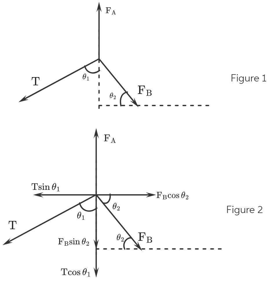
Figure 1 shows the direction of force in stunt A and stunt B.
Figure 2 shows the horizontal and the vertical components of all the forces.
Here,
 is the tension in the cable,
 is the force exerted by stunt A,
 is the force exerted by stunt B, and
 and
and  are the angles.
Given data:
format('truetype')%3Bfont-weight%3Anormal%3Bfont-style%3Anormal%3B%7D%3C%2Fstyle%3E%3C%2Fdefs%3E%3Ctext%20font-family%3D%22Arial%22%20font-size%3D%2216%22%20font-style%3D%22italic%22%20text-anchor%3D%22middle%22%20x%3D%224.5%22%20y%3D%2216%22%3E%26%23x3B8%3B%3C%2Ftext%3E%3Ctext%20font-family%3D%22Arial%22%20font-size%3D%2212%22%20text-anchor%3D%22middle%22%20x%3D%2213.5%22%20y%3D%2221%22%3E1%3C%2Ftext%3E%3Ctext%20font-family%3D%22math1ac5ee35ab114b9d293d11ac857%22%20font-size%3D%2216%22%20text-anchor%3D%22middle%22%20x%3D%2225.5%22%20y%3D%2216%22%3E%3D%3C%2Ftext%3E%3Ctext%20font-family%3D%22Arial%22%20font-size%3D%2216%22%20text-anchor%3D%22middle%22%20x%3D%2243.5%22%20y%3D%2216%22%3E64%3C%2Ftext%3E%3Ctext%20font-family%3D%22math1ac5ee35ab114b9d293d11ac857%22%20font-size%3D%2216%22%20text-anchor%3D%22middle%22%20x%3D%2256.5%22%20y%3D%2216%22%3E%26%23xB0%3B%3C%2Ftext%3E%3Ctext%20font-family%3D%22math1ac5ee35ab114b9d293d11ac857%22%20font-size%3D%2216%22%20text-anchor%3D%22middle%22%20x%3D%2262.5%22%20y%3D%2216%22%3E%2C%3C%2Ftext%3E%3Ctext%20font-family%3D%22Arial%22%20font-size%3D%2216%22%20font-style%3D%22italic%22%20text-anchor%3D%22middle%22%20x%3D%2273.5%22%20y%3D%2216%22%3E%26%23x3B8%3B%3C%2Ftext%3E%3Ctext%20font-family%3D%22Arial%22%20font-size%3D%2212%22%20text-anchor%3D%22middle%22%20x%3D%2282.5%22%20y%3D%2221%22%3E2%3C%2Ftext%3E%3Ctext%20font-family%3D%22math1ac5ee35ab114b9d293d11ac857%22%20font-size%3D%2216%22%20text-anchor%3D%22middle%22%20x%3D%2294.5%22%20y%3D%2216%22%3E%3D%3C%2Ftext%3E%3Ctext%20font-family%3D%22Arial%22%20font-size%3D%2216%22%20text-anchor%3D%22middle%22%20x%3D%22112.5%22%20y%3D%2216%22%3E49%3C%2Ftext%3E%3Ctext%20font-family%3D%22math1ac5ee35ab114b9d293d11ac857%22%20font-size%3D%2216%22%20text-anchor%3D%22middle%22%20x%3D%22125.5%22%20y%3D%2216%22%3E%26%23xB0%3B%3C%2Ftext%3E%3Ctext%20font-family%3D%22math1ac5ee35ab114b9d293d11ac857%22%20font-size%3D%2216%22%20text-anchor%3D%22middle%22%20x%3D%22131.5%22%20y%3D%2216%22%3E%2C%3C%2Ftext%3E%3Ctext%20font-family%3D%22Arial%22%20font-size%3D%2216%22%20font-style%3D%22italic%22%20text-anchor%3D%22middle%22%20x%3D%22143.5%22%20y%3D%2216%22%3ET%3C%2Ftext%3E%3Ctext%20font-family%3D%22math1ac5ee35ab114b9d293d11ac857%22%20font-size%3D%2216%22%20text-anchor%3D%22middle%22%20x%3D%22157.5%22%20y%3D%2216%22%3E%3D%3C%2Ftext%3E%3Ctext%20font-family%3D%22Arial%22%20font-size%3D%2216%22%20text-anchor%3D%22middle%22%20x%3D%22184.5%22%20y%3D%2216%22%3E2880%3C%2Ftext%3E%3Ctext%20font-family%3D%22Arial%22%20font-size%3D%2216%22%20text-anchor%3D%22middle%22%20x%3D%22212.5%22%20y%3D%2216%22%3EN%3C%2Ftext%3E%3C%2Fsvg%3E)

Trending now
This is a popular solution!

Step by step
Solved in 4 steps with 19 images


