A coil of resistance R and inductance L is connected in series with a 50 μF capacitor, figure If the supply voltage is V at 50 Hzand the current flowing in the circuit is 3L-30° A, determine the values of R and L. Determine also the voltage across the coil and the voltage across the capacitor. 1= 32-30° A Coil 220v 50 Hz VOOL Vc R 50 μF
A coil of resistance R and inductance L is connected in series with a 50 μF capacitor, figure If the supply voltage is V at 50 Hzand the current flowing in the circuit is 3L-30° A, determine the values of R and L. Determine also the voltage across the coil and the voltage across the capacitor. 1= 32-30° A Coil 220v 50 Hz VOOL Vc R 50 μF

Delmar's Standard Textbook Of Electricity
7th Edition
ISBN:9781337900348
Author:Stephen L. Herman
Publisher:Stephen L. Herman
Chapter20: Capacitance In Ac Circuits
Section: Chapter Questions
Problem 2PA: You are working in an industrial plant. You have been instructed to double the capacitance connected...

Related questions
Question
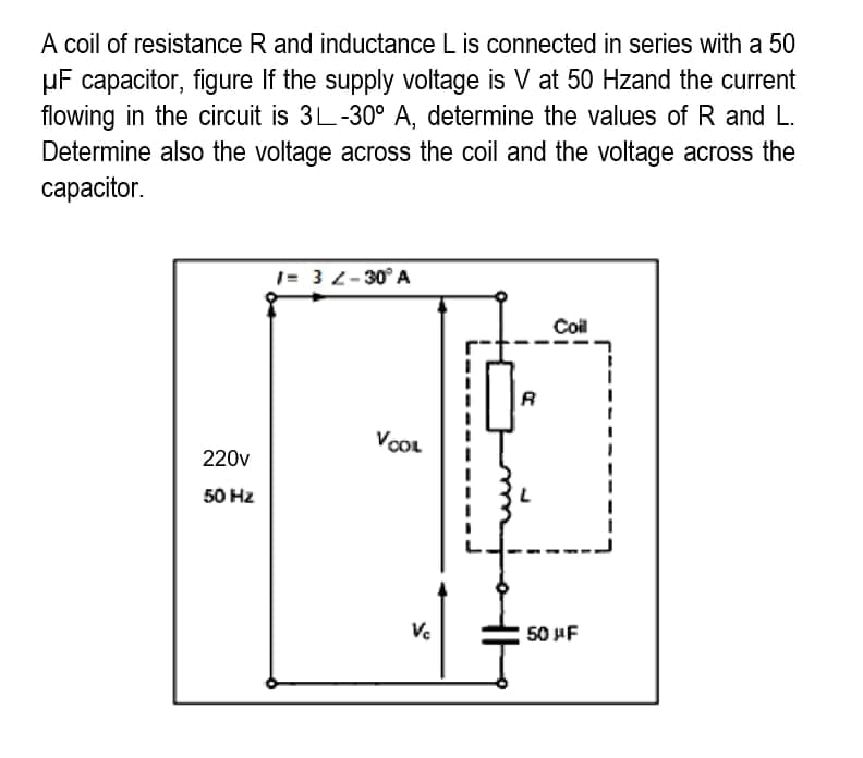
Transcribed Image Text:A coil of resistance R and inductance L is connected in series with a 50
μF capacitor, figure If the supply voltage is V at 50 Hzand the current
flowing in the circuit is 3L-30° A, determine the values of R and L.
Determine also the voltage across the coil and the voltage across the
capacitor.
1= 32-30° A
Coil
220v
50 Hz
VOOL
Vc
R
50 μF
Expert Solution
This question has been solved!
Explore an expertly crafted, step-by-step solution for a thorough understanding of key concepts.

Step by step
Solved in 3 steps with 2 images

Knowledge Booster


Learn more about
Need a deep-dive on the concept behind this application? Look no further. Learn more about this topic, electrical-engineering and related others by exploring similar questions and additional content below.Recommended textbooks for you
Delmar's Standard Textbook Of Electricity
Electrical Engineering
ISBN:
9781337900348
Author:
Stephen L. Herman
Publisher:
Cengage Learning
Delmar's Standard Textbook Of Electricity
Electrical Engineering
ISBN:
9781337900348
Author:
Stephen L. Herman
Publisher:
Cengage Learning