A common emitter BJT circuit is designed as shown in Fig. 4(a). The output load line and defined Q-point of the circuit are shown in Fig. Determine the required values of Vcc, Rc and RB. .Assume that VBE (on)=0.7 V
A common emitter BJT circuit is designed as shown in Fig. 4(a). The output load line and defined Q-point of the circuit are shown in Fig. Determine the required values of Vcc, Rc and RB. .Assume that VBE (on)=0.7 V

Chapter9: Current And Resistance
Section: Chapter Questions
Problem 46P: An electronic device designed to operate at any temperature in the range from 10.0C to 55.0C...

Related questions
Question
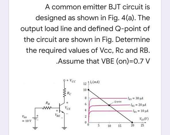
Transcribed Image Text:A common emitter BJT circuit is
designed as shown in Fig. 4(a). The
output load line and defined Q-point of
the circuit are shown in Fig. Determine
the required values of Vcc, Rc and RB.
Assume that VBE (on)=0.7 V
Vcc
12 e(ma)
10
RC
8.
-la 30 µA
Opoiet
R
ww
6
%3D
VCE
le = 10 uA
VBE
Van
= 10 V
Vee (V)
10
15
20
25
ww
Expert Solution
This question has been solved!
Explore an expertly crafted, step-by-step solution for a thorough understanding of key concepts.

Step by step
Solved in 2 steps with 2 images

Knowledge Booster


Learn more about
Need a deep-dive on the concept behind this application? Look no further. Learn more about this topic, physics and related others by exploring similar questions and additional content below.Recommended textbooks for you


Physics for Scientists and Engineers: Foundations…
Physics
ISBN:
9781133939146
Author:
Katz, Debora M.
Publisher:
Cengage Learning
Physics for Scientists and Engineers: Foundations…
Physics
ISBN:
9781133939146
Author:
Katz, Debora M.
Publisher:
Cengage Learning