A DC voltage is required to power a load that can be modeled as a simple resistor with R = 500 Ω. A sinusoidal voltage with peak value of VP = 10 V at a frequency of 60 Hz is available. Design a full-wave bridge rectifier circuit to accomplish this. Include a capacitor in parallel with the load to provide some filtering.
A DC voltage is required to power a load that can be modeled as a simple resistor with R = 500 Ω. A sinusoidal voltage with peak value of VP = 10 V at a frequency of 60 Hz is available. Design a full-wave bridge rectifier circuit to accomplish this. Include a capacitor in parallel with the load to provide some filtering.

Introductory Circuit Analysis (13th Edition)
13th Edition
ISBN:9780133923605
Author:Robert L. Boylestad
Publisher:Robert L. Boylestad
Chapter1: Introduction
Section: Chapter Questions
Problem 1P: Visit your local library (at school or home) and describe the extent to which it provides literature...

Related questions
Question
Need help designing circuit!
A DC voltage is required to power a load that can be modeled as a simple resistor with
R = 500 Ω. A sinusoidal voltage with peak value of VP = 10 V at a frequency of 60 Hz is
available. Design a full-wave bridge rectifier circuit to accomplish this. Include a capacitor in
parallel with the load to provide some filtering.
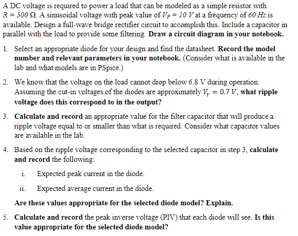
Transcribed Image Text:A DC voltage is required to power a load that can be modeled as a simple resistor with
R = 500 2. A sinusoidal voltage with peak value of Vp = 10 V at a frequency of ó0 Hz is
available. Design a full-wave bridge rectifier circuit to accomplish this. Include a capacitor in
parallel with the load to provide some filtering. Draw a circuit diagram in your notebook.
1. Select an appropriate diode for your design and find the datasheet. Record the model
number and relevant parameters in your notebook. (Consider what is available in the
lab and what models are in PSpice.)
2. We know that the voltage on the load cannot drop below 6.8 V during operation.
Assuming the cut-in voltages of the diodes are approximately V, = 0.7 V, what ripple
voltage does this correspond to in the output?
3. Calculate and record an appropriate value for the filter capacitor that will produce a
ripple voltage equal to or smaller than what is required. Consider what capacitor values
are available in the lab.
4. Based on the ripple voltage corresponding to the selected capacitor in step 3, calculate
and record the following:
i. Expected peak current in the diode.
ii. Expected average current in the diode.
Are these values appropriate for the selected diode model? Explain.
5. Calculate and record the peak inverse voltage (PIV) that each diode will see. Is this
value appropriate for the selected diode model?
Expert Solution
This question has been solved!
Explore an expertly crafted, step-by-step solution for a thorough understanding of key concepts.

This is a popular solution!

Trending now
This is a popular solution!

Step by step
Solved in 3 steps with 1 images

Knowledge Booster


Learn more about
Need a deep-dive on the concept behind this application? Look no further. Learn more about this topic, electrical-engineering and related others by exploring similar questions and additional content below.Recommended textbooks for you
Introductory Circuit Analysis (13th Edition)
Electrical Engineering
ISBN:
9780133923605
Author:
Robert L. Boylestad
Publisher:
PEARSON

Delmar's Standard Textbook Of Electricity
Electrical Engineering
ISBN:
9781337900348
Author:
Stephen L. Herman
Publisher:
Cengage Learning

Programmable Logic Controllers
Electrical Engineering
ISBN:
9780073373843
Author:
Frank D. Petruzella
Publisher:
McGraw-Hill Education
Introductory Circuit Analysis (13th Edition)
Electrical Engineering
ISBN:
9780133923605
Author:
Robert L. Boylestad
Publisher:
PEARSON
Delmar's Standard Textbook Of Electricity
Electrical Engineering
ISBN:
9781337900348
Author:
Stephen L. Herman
Publisher:
Cengage Learning
Programmable Logic Controllers
Electrical Engineering
ISBN:
9780073373843
Author:
Frank D. Petruzella
Publisher:
McGraw-Hill Education

Fundamentals of Electric Circuits
Electrical Engineering
ISBN:
9780078028229
Author:
Charles K Alexander, Matthew Sadiku
Publisher:
McGraw-Hill Education

Electric Circuits. (11th Edition)
Electrical Engineering
ISBN:
9780134746968
Author:
James W. Nilsson, Susan Riedel
Publisher:
PEARSON

Engineering Electromagnetics
Electrical Engineering
ISBN:
9780078028151
Author:
Hayt, William H. (william Hart), Jr, BUCK, John A.
Publisher:
Mcgraw-hill Education,