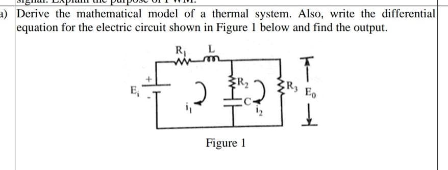
a) Derive the mathematical model of a thermal system. Also, write the differential equation for the electric circuit shown in Figure 1 below and find the output. R₁ E₁ ERz 화 Figure 1 R3 E0 뇨


Q: PART II. Given the linear mechanical system below: 2 N-s/m WITH_H_H_ 6 N/m 00004 kg x₁ (1) 2 N-s/m 4…
A: In this question We need to determine the transfer function. We are solving this problem using the…
Q: 1. GIVEN THE FollONING CLOSED LOOP SYSTEMS REDUCE THE BIOCK DIAGRAN TO A SINGIE TRANS FER FUNCTION…
A: As per guidelines i have answered only one . please ask remaining againthankyou.
Q: A.) A copper conductor of circular cross section 2 mm in diameter is 3 m long. Calculate its…
A: Given data, Length of wire L = 3 m. Diameter d=2 mm=2×10⁻³ m. Radius is given as,…
Q: In the figure shown, v1 lags v2 by * 90° 60° -90° -60° 13 1/1 12 H = 200µs/div and V₂ = 0.5V/div
A:
Q: Problem_#06] Derive the SOP and POS expression for the truth table shown below. хо ABC X 000 0 001 1…
A: Answer : given that a logic table for A ,B,C inputs to find sop and pos forms
Q: A current of 3A flows for 5 minutes. What charge is transferred?
A:
Q: What is the bandwidth in MBytes/s of a parallel data link that consists of 32 for data transfer, a…
A:
Q: Please show the work in between the rearranged formula and the answer
A: Given: Calculate the S/N in dB if the passband circuit is 48kHz to 64kHz and the maximum bit rate is…
Q: Consider the circuit shown in (Figure 1). Suppose that R = 100 kn. Figure 20 ΚΩ 3 ΚΩ 100 V 80 kn 1…
A:
Q: Gain Margin
A:
Q: Quiz #7 i 6 Part 3 of 5 L1 81 TD1-1 °Tss) TD1-2 °58) (5 s) TD2-1 °T° (5 s) TD2-2 °7° (5 s) (TD) PL1…
A: Given a logic diagram To find what happens to PL1,PL2,PL3 and PL4 if Switch S1 has been closed for 5…
Q: Series Current The supply across the terminals of this circuit is 450 V, 50 Hz. An ammeter is…
A:
Q: Determine the power supplied by the independent voltage source in the circuit where V=7, R1=7 and R2…
A: Determine the power supplied by the independent voltage source in the circuit where V=7 v, R1=7 ohm…
Q: I think I need help with the algebra in here. how do you arrive at 3/4 R1 . Also it os still…
A:
Q: Determine the value of R1 such that the Op Amps output, Vo, becomes saturated.
A: The given circuit is an non inverting amplifier and the required value of resistance can be…
Q: loov DETERMINE V₂ AND THE REQUIRED PIV RATING OF EACH DIODE FOR THE CIRCUIT BELOW- SKETCH THE OUTPUT…
A: In this question We need to determine the output voltage Vo, peak inverse voltage and sketch the…
Q: Let a causal LTI system be governed by the following differential equation y(t) + 1 dy 4 dt and y(t)…
A: Given data- A causal LTI system governed by following differential equation, yt+1dydt=2xt xt is…
Q: From the figure, the voltage Vc t>0 is equal to what?
A: We need to find the voltage Vc(t) for t>0.
Q: A sinusoidal voltage trace displayed by an oscilloscope is shown, if the 'time/div' or Hs, switch is…
A:
Q: The supply across the terminals of this circuit is 330 V, 50 Hz. An ammeter is connected to the…
A: It is given that: V=330 Vf=50 HzL=350 mHI=10 A
Q: 10.44 Find all currents and voltages in the network in Fig. P10. 12/0° V +1 ww I 1Ω + V₁ - 1:2 Ideal…
A: I have written this solution as handwritten solution. Hope you find the solution clear.
Q: 3. lov 262 2 kr ovo 222
A: Answer: given that a liner circuit consists of silicon diode( cut-off voltage = 0.7 V) and one is…
Q: A 230-V industrial electric fan takes a current of 2 A. If the energy cost P12.00 per kWH, estimate…
A: In this question we need to find the estimate cost per month of the electrical fan
Q: Assume the initial cost to set up a thermal power plant of 100 MW is 2 million dollars and that of a…
A:
Q: An RLC series resonance circuit has a resonance frequency of (5000/2π) Hz and impedance at resonance…
A:
Q: The equation of v1 in the figure shown if Vs = 200mV/div is * O 500sin1667πt volts O…
A: Given Data: A waveform of a sinusoidal voltage V1 with the scale of, In the x-axis 1 division = 200…
Q: In the figure shown, if t = 0.3 mS, v1 is equivalent to * 0.707 V OV 0.5 V O 1 V H = 200µs/div and…
A: In this question We need to determine the value of voltage V1 (t) at time t= 0.3ms Assume sinusoidal…
Q: Based on the amplifier given in Fig. 2, draw the small signal equivalent and derive the two time…
A: The ac amplifier circuit is given as According to the datasheet of the 2N3904, the DC current gain…
Q: Considering terminals a and b: a) Use any method to solve for the Thevenin equivalent voltage. b)…
A: The thevenin's equivalent circuit can be obtained by calculating the open circuit voltage and…
Q: 3. Calculate the final resistance of a copper wire at twice the temperature which is initially 300…
A: Given, T1=100°CR1= 30 ohmT2=2T1(Resistance at twice the temperature)T2=2×100°CT2= 200°C α=…
Q: QUESTION 5 The differences between a standard PLC and a safety PLC are: A standard PLC has one…
A: We need select correct option for given statement.
Q: Problem 4-For the circuit shown, V1-2020 V, 0-377 rad/s and the load is 10/30°02. a) Find the…
A:
Q: A 40 MVA, 11 KV, 3-phase, 50 Hz, 4-pole turbo alternator has an inertia constant of 15 sec. An input…
A: input power = Pin = 20 MWoutput power = Pout = 15MWgiven frequency = f =50 Hzinertia constant = H…
Q: From the figure, the voltage Vc at t = (0+) is equal to?
A: Given:
Q: In the unity feedback system, what is the system type and find the appropriate steady-state error…
A: In this question We need to determine the type of the system, error constant and error for different…
Q: What is the minimum sized PVC Schedule 80 conduit we should use for the above wire run if it is over…
A: To determine the minimum sized PVC Schedule 80 conduit needed for the above wire run if it is over…
Q: What is pulse width modulation (PWM) and how is it used in power electronics?
A: Pulse width modulation (PWM) is a technique used in power electronics to control the amount of power…
Q: what is t=0-
A: Given: What is t=0-?
Q: Use the following diode circuit to answer the questions that follow: D1 M 2k -5V +5V D2 4k D2 + V₂
A:
Q: Which logic gate is implemented by using the MUX A 4 0 1 2x1-Y B
A: Given: The logic multiplexer circuit,
Q: Find the SNR in a baseband system with a bandwidth of 5 KHz and no = 10-14 W/Hz. The transmitted…
A: I have written this solution as handwritten solution. Hope you find the solution clear.
Q: Project # 3: Wheastone Bridge + V Wheatstone Bridge 12 VDC R₁ io. R3 ECE 201 Circuit Theory I R₂…
A:
Q: Us A 2~ 2 What is the Electric Field at P₁ What is the Electrostatic Potential P₁ at Pi? Q₁ V x
A:
Q: In the circuit shown, the voltage across R1 at t = (0+) is equal t Vs 10V R₁ 7 V O 4 V 6 V 322 Vc Ic…
A: Properties of capacitor: At t =0-, capacitor acts like open circuit. Voltage across capacitor does…
Q: A uniform two-wire DC distributor that is 200 m long is loaded with 2 amperes/meter. Resistance of…
A: Given- A uniform two-wire DC distributor- length L=200 m, Current = 2 amperes/meter, Resistance =…
Q: Vs 10V R₁ 30 + Vc Ic 7F R₂ ww 202 SW t=0 Sw
A:
Q: 1- Indicate, on the circuit, the reference direction of the current flowing in the circuit. 2-…
A: The current flows from higher potential to lower potential and based on that the current direction…
Q: Q2) Use mesh analysis to find the voltage "V." in the circuit shown 1 ΚΩ I, 1ΚΩ Μ + )12V TRAI 51 ΚΩ…
A:
Q: Problem 3-An AC circuit is shown. The frequency is 1000 Hz. The source voltage is v(t)- 10…
A:
Q: In an R-L series circuit, ET = 240 volts, R = 60 2, and XL = 75 Q. Find EL. O 187.4 V O 96.04 V O…
A: Given data ET=240 V R=60Ω XL=75 Ω To find out Voltage across the inductor L, EL

Step by step
Solved in 2 steps with 2 images


- The electrical model of a biopotential electrode is given belowwith the given values. (a)Plot the absolute impedance of this electrode(i.e.,|Z|) with respect to the frequency using a python script and (b) discuss the frequency range to reachthe minimum absolute impedance value on this electrode. Rd:26 kΩ Rs: 6 kΩQ1) Conduct an evaluation on the practical applications of the concepts of electromagnetism and submit a written report which includes the following. a) Design a circuit which utilizes the concept of electromagnetism and submit a simulation circuit for the same (use simulation tool of your choice) b) Write down the selected values of the components used for example the values of resistors, transistor used, capacitors etc c) Obtain the output for the ciruit using any sinks like CRO, loud speakers etc. d) Discuss about the principles of electromagnetism used in the simulation I WANT QUESTION (D)Five years ago, when the relevant cost index was 120, a nuclear centrifuge cost $40,000. The centrifuge had a capacity of separating 1500 gallons of ionized solution per hour. Today, the boss wants to build a centrifuge with capacity of 4500 gallons per hour, but the cost index now is 300. Assuming a power-sizing exponent of 0.75, determine the approximate cost in today's dollars of the new, larger reactor
- Explain, with the aid of a circuit diagram, how ad.c. voltmeter may be calibrated by means of a potentiometer method.A moving-coil instrument, used as a voltmeter, hasa coil of 150 turns with a width of 3 cm and an activelength of 3 cm. The gap flux density is 0.15 T. If thefull-scale reading is 150 V and the total resistance ofthe instrument is 100 000 Ω, find the torque exertedby the control springs at full scale.The following parameters are used in an EDM process, the supply voltage is 150V. The resistance and capacitance in the circuit are 50 Ohms and 15 microfarads respectively. The tool is made of brass and kerosene is used as the dielectric. A hole diameter of 20 mm is to be cut into a plate of thickness of 3mm. If the discharge takes place at maximum power conditions. The value of constant K4=0.18, calculate the MRR, and machining time.Electrical Engineering - Power System Analysis Please solve the question quickly
- Write the differential equation for t > 0 for iC in the given figure. Assume VS = 9 V, RS = 4 kohm, R1 = 11 kohm, and R2 = R3 = 20 kohm.Q 03: Briefly discuss, how the energy consumptions for operations of a fork lifter could be justified. Suppose that a fork lifter has a total energy consumption of 150 W.Hr. The total trips of the vehicle are 375. How the battery duty cycle may be calculated in this case?Please answer the following points in detail and rigorously. Instead ofresort to formulas, develop from basic principles (laws ofvoltages and currents, definition of electrical power, properties ofphasors, among others) a) Suppose that between the two terminals of an element there is a voltage v (t) and that through the terminal marked with a positive sign a current i (t). Show that if v (t) and i (t) are sinusoidal and are out of phase an angle θ, then the active power P which is consumed by this element is proportional to cosθ. b) How much is P for a pure inductor and how much for a capacitor pure? Does this make physical sense? c) When the power factor seen between two terminals is specified, Why is it necessary to indicate whether it is late or early? d) Show that the complex power consumed by two elements in parallel is the sum of the individual complex powers. After, repeat the procedure but for two elements in series. e) What meaning would you give to the P consumed by an…
- how to find I0? (Basic Engineering Circuit Analysis)Find the values of input and output power. The weight of the car is 800 Kg The weight of each person is 75 Kg You may assume any missing parameters you need in the design appropriately (e.g., the rolling-resistance-power, air-resistance-power, the DC motor's parameters, ....etc)Exercise 3: In the circuit of figure below, the diode is assumed to be perfect. The transformer secondary has zero resistance and delivers voltage ve(t)= V msin wt. 1. Draw the waveform of vs(t) when the capacitor is disconnected. 2. The capacitor being switched on, we assume that the start of the charge is at time t = 0. a. Give the expression of the current i(t); we will then suppose x(t) = wt b. Determine the angle x1(t) = wt, of the end of conduction of the diode. 3. When the diode has stopped conducting, what is the equivalent circuit in figure below? Write the differential equation governing this circuit. Give its general solution. Deduce the expression of vs(t) for the discharge phase of the capacitor. 4. Write the mathematical condition corresponding to the angle x2(t) = wt2 end of discharge of the capacitor. 5. Deduce the approximate waveform from the filtered voltage Vs(t).