Q2. Consider the single-phase transformer circuit shown below. Transformer ratings and reactances are: Transformer A : 200 kVA, 250 / 750 V , X = 0.10 p.u. Transformer B : 100 kVA , 900 / 300 V , X= 0.15 p.u. The transmission line can be represented as a series impedance Zine 0.4 +j 0.6 N. Choose a base of 200 kVA, 250 V in the voltage source ( V, ) circuit. (a) Draw the impedance diagram for this circuit, with all impedances in per unit. (b) Find the load voltage in per unit and in volts when the source voltage is V.-120° pu. (c) Find the transmission line current (IL) in amperes. transmission line A (Zn-0.4 + j0.6 N) B "line IL Z=0.5 + j0.2 Q Leeee lell Leeee
Q2. Consider the single-phase transformer circuit shown below. Transformer ratings and reactances are: Transformer A : 200 kVA, 250 / 750 V , X = 0.10 p.u. Transformer B : 100 kVA , 900 / 300 V , X= 0.15 p.u. The transmission line can be represented as a series impedance Zine 0.4 +j 0.6 N. Choose a base of 200 kVA, 250 V in the voltage source ( V, ) circuit. (a) Draw the impedance diagram for this circuit, with all impedances in per unit. (b) Find the load voltage in per unit and in volts when the source voltage is V.-120° pu. (c) Find the transmission line current (IL) in amperes. transmission line A (Zn-0.4 + j0.6 N) B "line IL Z=0.5 + j0.2 Q Leeee lell Leeee

Power System Analysis and Design (MindTap Course List)
6th Edition
ISBN:9781305632134
Author:J. Duncan Glover, Thomas Overbye, Mulukutla S. Sarma
Publisher:J. Duncan Glover, Thomas Overbye, Mulukutla S. Sarma
Chapter3: Power Transformers
Section: Chapter Questions
Problem 3.65P: Reconsider Problem 3.64 with the change that now Tb includes both a transformer of the same turns...

Related questions
Question
Electrical Engineering - Power System Analysis
Please solve the question quickly
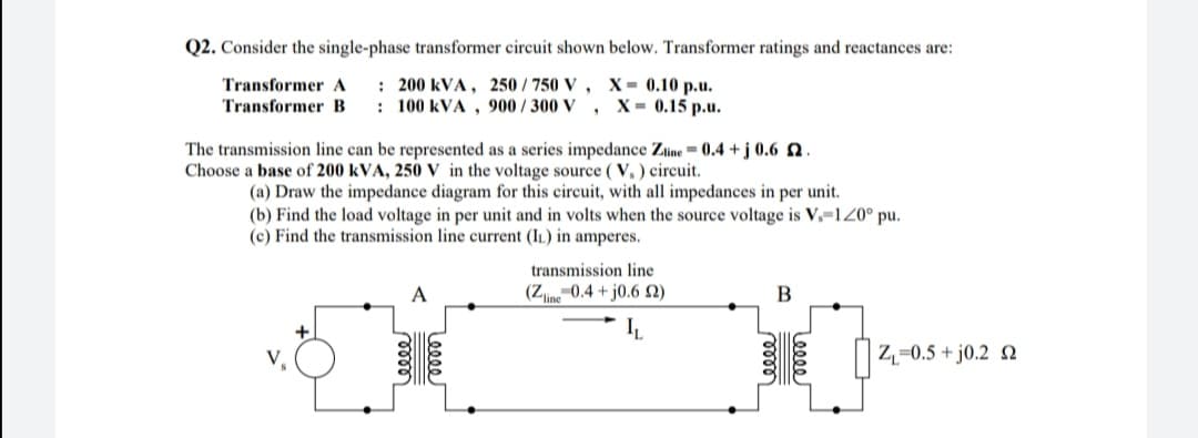
Transcribed Image Text:Q2. Consider the single-phase transformer circuit shown below. Transformer ratings and reactances are:
: 200 kVA , 250 / 750 V , X = 0.10 p.u.
: 100 kVA , 900 / 300 V
Transformer A
Transformer B
X- 0.15 р.u.
The transmission line can be represented as a series impedance Zine = 0.4 + j 0.6 N.
Choose a base of 200 kVA, 250 V in the voltage source ( V, ) circuit.
(a) Draw the impedance diagram for this circuit, with all impedances in per unit.
(b) Find the load voltage in per unit and in volts when the source voltage is V.-120° pu.
(c) Find the transmission line current (IL) in amperes.
transmission line
(Z0.4 + j0.6 N)
Z,=0.5 + j0.2 N
Leeee
Expert Solution
This question has been solved!
Explore an expertly crafted, step-by-step solution for a thorough understanding of key concepts.

Step by step
Solved in 3 steps with 2 images

Knowledge Booster


Learn more about
Need a deep-dive on the concept behind this application? Look no further. Learn more about this topic, electrical-engineering and related others by exploring similar questions and additional content below.Recommended textbooks for you
Power System Analysis and Design (MindTap Course …
Electrical Engineering
ISBN:
9781305632134
Author:
J. Duncan Glover, Thomas Overbye, Mulukutla S. Sarma
Publisher:
Cengage Learning

Electricity for Refrigeration, Heating, and Air C…
Mechanical Engineering
ISBN:
9781337399128
Author:
Russell E. Smith
Publisher:
Cengage Learning
Power System Analysis and Design (MindTap Course …
Electrical Engineering
ISBN:
9781305632134
Author:
J. Duncan Glover, Thomas Overbye, Mulukutla S. Sarma
Publisher:
Cengage Learning
Electricity for Refrigeration, Heating, and Air C…
Mechanical Engineering
ISBN:
9781337399128
Author:
Russell E. Smith
Publisher:
Cengage Learning