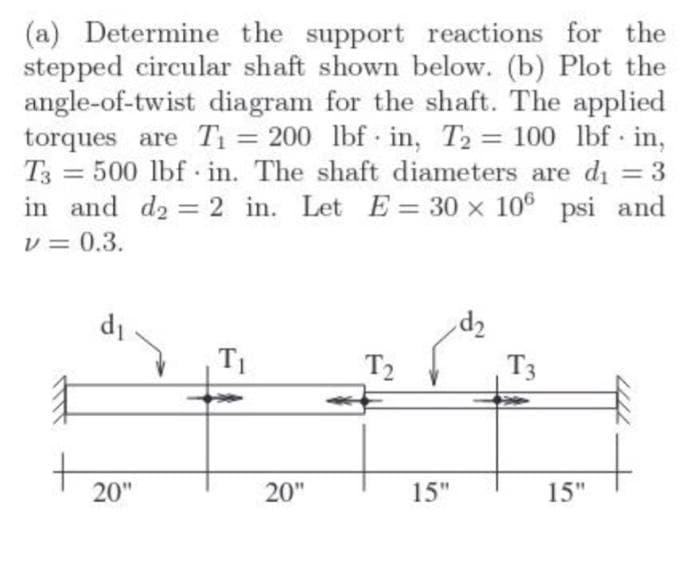
(a) Determine the support reactions for the stepped circular shaft shown below. (b) Plot the angle-of-twist diagram for the shaft. The applied torques are T1 = 200 lbf in, T2 100 lbf in, = 500 lbf in. The shaft diameters are di = 3 %3D T3 %3D in and d2 = 2 in. Let E = 30 x 106 psi and v = 0.3. 7p T3 T2 20" 20" 15" 15"
(a) Determine the support reactions for the stepped circular shaft shown below. (b) Plot the angle-of-twist diagram for the shaft. The applied torques are T1 = 200 lbf in, T2 100 lbf in, = 500 lbf in. The shaft diameters are di = 3 %3D T3 %3D in and d2 = 2 in. Let E = 30 x 106 psi and v = 0.3. 7p T3 T2 20" 20" 15" 15"

Mechanics of Materials (MindTap Course List)
9th Edition
ISBN:9781337093347
Author:Barry J. Goodno, James M. Gere
Publisher:Barry J. Goodno, James M. Gere
Chapter3: Torsion
Section: Chapter Questions
Problem 3.8.3P: A solid circular shaft AB of diameter d is fixed against rotation at both ends (sec figure), A...

Related questions

Question
Transcribed Image Text:(a) Determine the support reactions for the
stepped circular shaft shown below. (b) Plot the
angle-of-twist diagram for the shaft. The applied
torques are T1 = 200 lbf in, T2 = 100 lbf in,
= 500 lbf in. The shaft diameters are di =3
%3D
T3
in and d2 = 2 in. Let E = 30 x 10° psi and
v = 0.3.
%3D
7p
T3
d1
T2
20"
20"
15"
15"
Expert Solution
This question has been solved!
Explore an expertly crafted, step-by-step solution for a thorough understanding of key concepts.

This is a popular solution!

Trending now
This is a popular solution!

Step by step
Solved in 2 steps with 1 images

Knowledge Booster


Learn more about
Need a deep-dive on the concept behind this application? Look no further. Learn more about this topic, mechanical-engineering and related others by exploring similar questions and additional content below.Recommended textbooks for you
Mechanics of Materials (MindTap Course List)
Mechanical Engineering
ISBN:
9781337093347
Author:
Barry J. Goodno, James M. Gere
Publisher:
Cengage Learning
Mechanics of Materials (MindTap Course List)
Mechanical Engineering
ISBN:
9781337093347
Author:
Barry J. Goodno, James M. Gere
Publisher:
Cengage Learning