А M H B W Figure-2

Mechanics of Materials (MindTap Course List)
9th Edition
ISBN:9781337093347
Author:Barry J. Goodno, James M. Gere
Publisher:Barry J. Goodno, James M. Gere
Chapter6: Stresses In Beams (advanced Topics)
Section: Chapter Questions
Problem 6.5.7P: The cross section of a steel beam is constructed of a W 18 × 71 wide-flange section with a 6 in. ×...

Related questions

Question
Transcribed Image Text:y
M
B
H
B
W
Figure-2
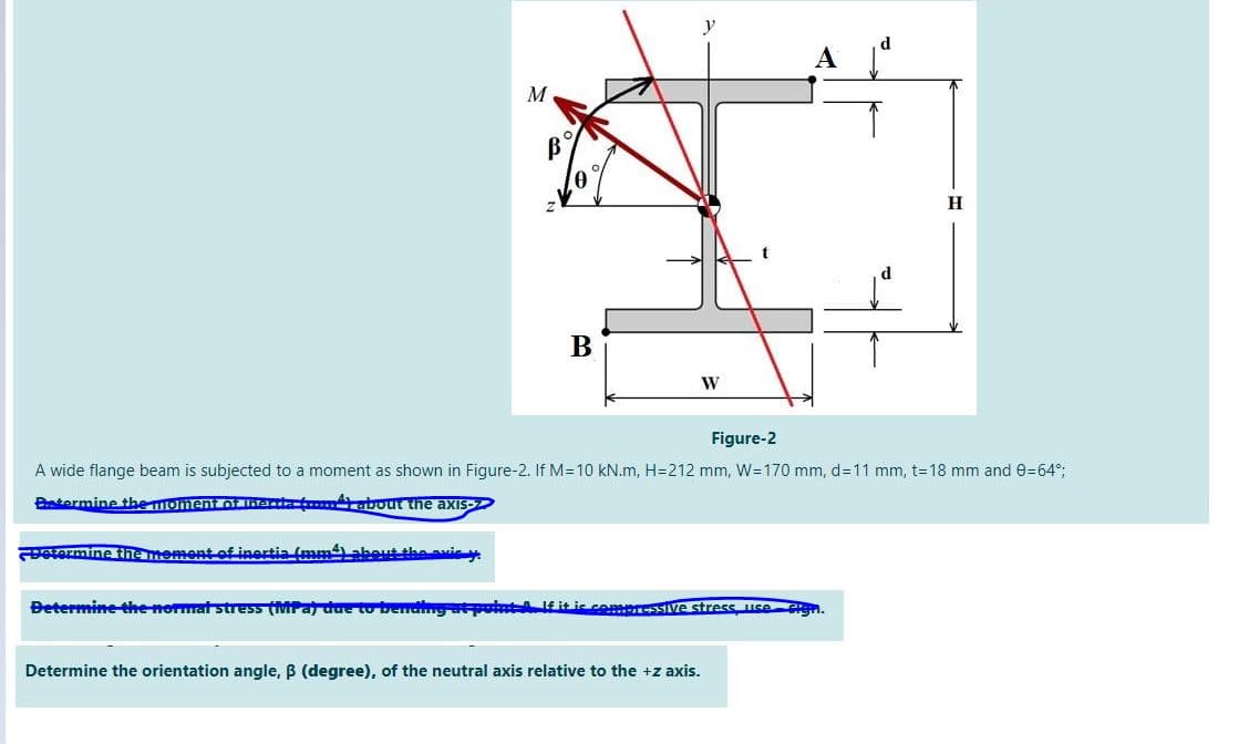
A wide flange beam is subjected to a moment as shown in Figure-2. If M=10 kN.m, H=212 mm, W=170 mm, d=11 mm, t=18 mm and 0=64°;
Btermine the momentOt lhadat about the axis-
etermine the mement of inertia (mmabeut the avie y
Betermine the normat stress (MPa due to bendng atpontA itic commressIive stress use
Determine the orientation angle, B (degree), of the neutral axis relative to the +z axis.
Expert Solution
This question has been solved!
Explore an expertly crafted, step-by-step solution for a thorough understanding of key concepts.

Step by step
Solved in 2 steps

Knowledge Booster


Learn more about
Need a deep-dive on the concept behind this application? Look no further. Learn more about this topic, mechanical-engineering and related others by exploring similar questions and additional content below.Recommended textbooks for you
Mechanics of Materials (MindTap Course List)
Mechanical Engineering
ISBN:
9781337093347
Author:
Barry J. Goodno, James M. Gere
Publisher:
Cengage Learning
Mechanics of Materials (MindTap Course List)
Mechanical Engineering
ISBN:
9781337093347
Author:
Barry J. Goodno, James M. Gere
Publisher:
Cengage Learning