A piping system is to be installed at place where the pump will transfer the fluid from tank A to tank B. There are two suggested piping designs available to carry the fluid efficiently. Compute and determine which of the available piping arrangement will experience the less pumping power with given flow conditions. Discuss the results. Flow conditions are same for both type of designs and given as: Pipe material: stainless steel Volume flow rate: 40 L/sec Assume the working fluid is water at standard atmosphere temperature and both tanks are open to atmosphere. Pipe inlet is sharp-edged and bends are sharped without vanes. Elevations are as ?? = ?? ? and ?? = ?? ?
A piping system is to be installed at place where the pump will transfer the fluid from tank A to tank B. There are two suggested piping designs available to carry the fluid efficiently. Compute and determine which of the available piping arrangement will experience the less pumping power with given flow conditions. Discuss the results. Flow conditions are same for both type of designs and given as: Pipe material: stainless steel Volume flow rate: 40 L/sec Assume the working fluid is water at standard atmosphere temperature and both tanks are open to atmosphere. Pipe inlet is sharp-edged and bends are sharped without vanes. Elevations are as ?? = ?? ? and ?? = ?? ?

Elements Of Electromagnetics
7th Edition
ISBN:9780190698614
Author:Sadiku, Matthew N. O.
Publisher:Sadiku, Matthew N. O.
ChapterMA: Math Assessment
Section: Chapter Questions
Problem 1.1MA

Related questions
Question
A piping system is to be installed at place where the pump will transfer the fluid from tank A to tank B. There are two suggested piping designs available to carry the fluid efficiently. Compute and determine which of the available piping arrangement will experience the less pumping power
with given flow conditions. Discuss the results.
Flow conditions are same for both type of designs and given as:
Pipe material: stainless steel
Volume flow rate: 40 L/sec
Assume the working fluid is water at standard atmosphere temperature and both tanks are
open to atmosphere.
Pipe inlet is sharp-edged and bends are sharped without vanes.
Elevations are as ?? = ?? ? and ?? = ?? ?
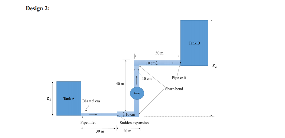
Transcribed Image Text:Design 2:
Tank B
30 m
10 cm
Z2
10 cm
Pipe exit
40 m
Sharp bend
Pump
Tank A
Dia = 5 cm
† 10 cm
Pipe inlet
Sudden expansion
30 m
20 m
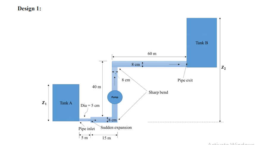
Transcribed Image Text:Design 1:
Tank B
60 m
8 cm
Z2
8 cm
Pipe exit
40 m
Sharp bend
Pump
Z1
Tank A
Dia = 5 cm
†8 cm
Pipe inlet Sudden expansion
5 m
15 m
Activate Window
Expert Solution
This question has been solved!
Explore an expertly crafted, step-by-step solution for a thorough understanding of key concepts.

Step by step
Solved in 4 steps with 4 images

Knowledge Booster


Learn more about
Need a deep-dive on the concept behind this application? Look no further. Learn more about this topic, mechanical-engineering and related others by exploring similar questions and additional content below.Recommended textbooks for you
Elements Of Electromagnetics
Mechanical Engineering
ISBN:
9780190698614
Author:
Sadiku, Matthew N. O.
Publisher:
Oxford University Press

Mechanics of Materials (10th Edition)
Mechanical Engineering
ISBN:
9780134319650
Author:
Russell C. Hibbeler
Publisher:
PEARSON

Thermodynamics: An Engineering Approach
Mechanical Engineering
ISBN:
9781259822674
Author:
Yunus A. Cengel Dr., Michael A. Boles
Publisher:
McGraw-Hill Education
Elements Of Electromagnetics
Mechanical Engineering
ISBN:
9780190698614
Author:
Sadiku, Matthew N. O.
Publisher:
Oxford University Press
Mechanics of Materials (10th Edition)
Mechanical Engineering
ISBN:
9780134319650
Author:
Russell C. Hibbeler
Publisher:
PEARSON
Thermodynamics: An Engineering Approach
Mechanical Engineering
ISBN:
9781259822674
Author:
Yunus A. Cengel Dr., Michael A. Boles
Publisher:
McGraw-Hill Education

Control Systems Engineering
Mechanical Engineering
ISBN:
9781118170519
Author:
Norman S. Nise
Publisher:
WILEY

Mechanics of Materials (MindTap Course List)
Mechanical Engineering
ISBN:
9781337093347
Author:
Barry J. Goodno, James M. Gere
Publisher:
Cengage Learning

Engineering Mechanics: Statics
Mechanical Engineering
ISBN:
9781118807330
Author:
James L. Meriam, L. G. Kraige, J. N. Bolton
Publisher:
WILEY