(a) Plot the data as engineering stress versus engineering strain. (b) Compute the modulus of elasticity. (c) Determine the yield strength at a strain offset of 0.002.
(a) Plot the data as engineering stress versus engineering strain. (b) Compute the modulus of elasticity. (c) Determine the yield strength at a strain offset of 0.002.

Elements Of Electromagnetics
7th Edition
ISBN:9780190698614
Author:Sadiku, Matthew N. O.
Publisher:Sadiku, Matthew N. O.
ChapterMA: Math Assessment
Section: Chapter Questions
Problem 1.1MA

Related questions
Question
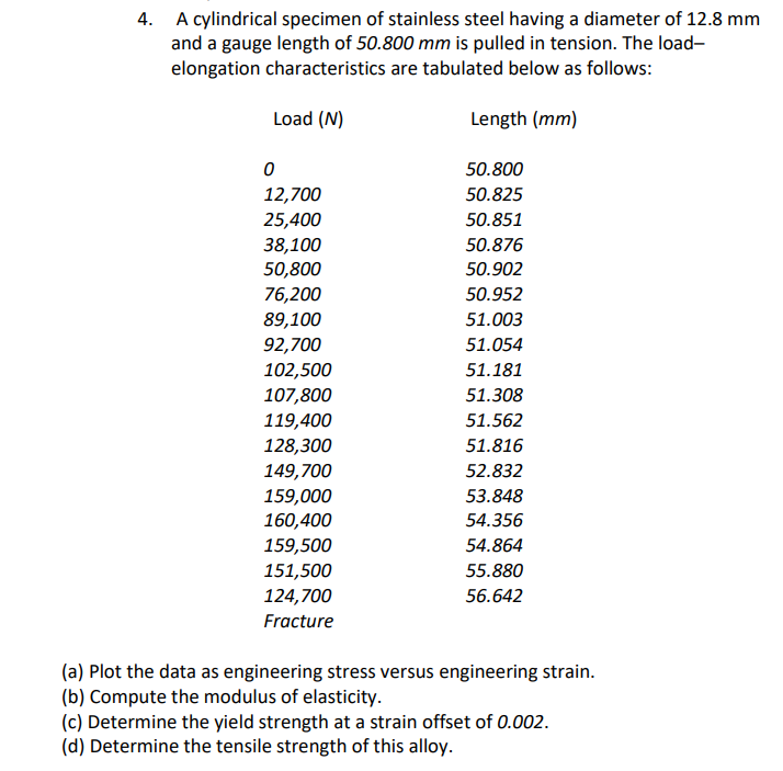
Transcribed Image Text:4. A cylindrical specimen of stainless steel having a diameter of 12.8 mm
and a gauge length of 50.800 mm is pulled in tension. The load-
elongation characteristics are tabulated below as follows:
Load (N)
Length (mm)
0
12,700
25,400
38,100
50,800
76,200
89,100
92,700
102,500
107,800
119,400
128,300
149,700
159,000
160,400
159,500
151,500
124,700
Fracture
50.800
50.825
50.851
50.876
50.902
50.952
51.003
51.054
51.181
51.308
51.562
51.816
52.832
53.848
54.356
54.864
55.880
56.642
(a) Plot the data as engineering stress versus engineering strain.
(b) Compute the modulus of elasticity.
(c) Determine the yield strength at a strain offset of 0.002.
(d) Determine the tensile strength of this alloy.
Expert Solution
This question has been solved!
Explore an expertly crafted, step-by-step solution for a thorough understanding of key concepts.

Step by step
Solved in 5 steps with 3 images

Knowledge Booster


Learn more about
Need a deep-dive on the concept behind this application? Look no further. Learn more about this topic, mechanical-engineering and related others by exploring similar questions and additional content below.Recommended textbooks for you
Elements Of Electromagnetics
Mechanical Engineering
ISBN:
9780190698614
Author:
Sadiku, Matthew N. O.
Publisher:
Oxford University Press

Mechanics of Materials (10th Edition)
Mechanical Engineering
ISBN:
9780134319650
Author:
Russell C. Hibbeler
Publisher:
PEARSON

Thermodynamics: An Engineering Approach
Mechanical Engineering
ISBN:
9781259822674
Author:
Yunus A. Cengel Dr., Michael A. Boles
Publisher:
McGraw-Hill Education
Elements Of Electromagnetics
Mechanical Engineering
ISBN:
9780190698614
Author:
Sadiku, Matthew N. O.
Publisher:
Oxford University Press
Mechanics of Materials (10th Edition)
Mechanical Engineering
ISBN:
9780134319650
Author:
Russell C. Hibbeler
Publisher:
PEARSON
Thermodynamics: An Engineering Approach
Mechanical Engineering
ISBN:
9781259822674
Author:
Yunus A. Cengel Dr., Michael A. Boles
Publisher:
McGraw-Hill Education

Control Systems Engineering
Mechanical Engineering
ISBN:
9781118170519
Author:
Norman S. Nise
Publisher:
WILEY

Mechanics of Materials (MindTap Course List)
Mechanical Engineering
ISBN:
9781337093347
Author:
Barry J. Goodno, James M. Gere
Publisher:
Cengage Learning

Engineering Mechanics: Statics
Mechanical Engineering
ISBN:
9781118807330
Author:
James L. Meriam, L. G. Kraige, J. N. Bolton
Publisher:
WILEY