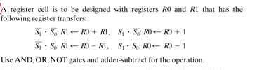
A register cell is to be designed with registers RO and R1 that has the following register transfers: 5, · 5; R1 – RO + RI, §; · 5; RO– RO + 1 S- S; RI- RD – RI, S · S: RO– RD – 1 Use AND, OR, NOT gates and adder-subtract for the operation.


Q: Can you call a DECODER as a DEMUX? If yes, in which case that could be. Design a DEMUX using simple…
A: The major distinction between a demultiplexer and a decoder is that the former is a combinational…
Q: Microprocessor Systems Question: A 20-bit address bus, an 8-bit processor uses a 3-to-8 decoder to…
A: The solution can be achieved as follows.
Q: Question 5 With reference to 8086 Microprocessors Pin Assignment: 1) State the three groups of…
A:
Q: A) Place the decimal number 27 into the R7 register. What would the contents of that register be…
A: “Since you have asked multiple questions, we will solve the first question for you. If you want any…
Q: Assume that the exclusive-OR gate has a contamination delay of 10 ns and that the AND or OR gates…
A:
Q: 2. How can a serial in/parallel out register be used as a serial in/serial out register?
A:
Q: Question Implement the Function 'Y = ACB + BC + E' using a 4-Input, 2-Address Bit Multiplexer. What…
A:
Q: S Display will be designed for a thermometer. The display will show that degree for minimum…
A: As per our policy we can provide solution of first three questions only. For a) As given, the…
Q: Design a 4-bit up/down gray counter?
A:
Q: 2- Construct a full-Adder logic circuit by using NAND gates only. 3- Construct a full- Subtractor…
A: The solution of the following questions are
Q: In PLD, any of this process is called Programming?? O a. Blowing fuse O b. Read and write data o.…
A: Programmable Logic Devices are the integrated circuits. They contain an array of AND and OR gates.…
Q: The upper 16-bits of the 40-bit binary count value are displayed on the four seven-segment displays…
A: The DAC is an digital to analog convertor. The machines understand the digital binary bits in their…
Q: Derive the equation for probability of bit error in a binary PAM system using the simple PAM…
A: According to the question, we need to derive the equation for the probability of bit error in the…
Q: . If a 6-bit binary number is used to represent an analog value in the range from -63 to 126, what…
A: According to given question, analog value range 63 to 126 6 bit binary number is used to represent…
Q: Assume SS=5000H, DS=6000H, ES=7000H, CS=9000H, BX=1000H, DI=2000H, BP=3000H, IP=4000H, SI=2000H, the…
A:
Q: On the same fashion, describe the path followed by the value of INTERNAL SIGNAL towards P0.x (see…
A: Port 0 can be used as an input/output or a bidirectional data bus and lower order address for…
Q: i) Analyse and execute the following 8051 Instructions and specify the output and explain the…
A: As per company guidelines we can solve only first question kindly post another question separately
Q: using the multiplexer design approach should bé 8- Assuming that a certain ASM chart has 5 states,…
A:
Q: What is the use of OPERANDS and FLAGS in execution unit?
A: Here we have to explain the use of operations and FLAGS in execution unit.
Q: Implement the following Boolean function by using 4x1 multiplexer. ����(?, ?, ?, ?) =…
A: As per Bartleby guidelines we are allowed to solve only one question, please ask the rest again.
Q: d) This addressing mode is always used to access memory, shown here as the source operand of this…
A: LDR R1, [R0]; Load into R0 the contents of the memory location pointed to by R3 This is Register…
Q: What Is branch datapath?
A: Branch datapath : A datapath which is also written as data path is the path which consist of…
Q: Design a micro programmed system that adds two 16-bit numbers stored in the register pair AB and CD…
A:
Q: The upper 16 -bit binary count value are displayed on the four seven -segemnt displays as four…
A: The DAC is an digital to analog convertor. The machines understand the digital binary bits in their…
Q: Design a 4-to-1 multiplexer using a 2-to-4 decoder and only AND and OR gates? Briefly explain how…
A:
Q: 2. Design the following Boolean function using appropriate Multiplexer and logic gates F(A, B, C, D)…
A: The given logic expression is:
Q: Describe what a 16-to-1 one-bit multiplexer does. Write a Boolean expression that implements this…
A: Multiplexer is a combinational circuit that consist of n selection lines, and 2n data inputs. These…
Q: HiW. for Bipolar +A logict → A+n. -A logico→-An Vth ?? Prove> -> %3D
A: SNR is defined as the ratio of signal power to the noise power. SNR=Signal power Noise power SNR in…
Q: How many bits are required to represent the Arduino analog input? Hint: There are 1024 possible…
A:
Q: Subject is Communication system. In a public switch telephone network (PSTN),how the analog speech…
A: There are majorly three steps for converting analog signal to digital signal. 1. Sampling of the…
Q: Write a Verilog code for 8-bit up/down counter for any type of Modeling.
A:
Q: Q1) Write a control sequence execution of the following instruction for the single bus data path a)…
A:
Q: Refer to the following registers values and memory snippet to answer the following questions.…
A: The 8086 microprocessor is a 16 bit microprocessor with 16 data lines and 20 address lines. It is…
Q: VHDL Difference between function and task. What is logic data type.
A: Bit is 2 state data type. It can take 0 and 1 only. Reg is driven by always block it can't be…
Q: Q4. A common bus system which is capable of transferring 2 bits at time with number of registers are…
A: Multiplexer- A multiplexer is a device that is used to select one of several input signals and send…
Q: Suppose we have two registers, Rl and R2, and between them we have a combinational logic circuit.…
A: Formula of maximum frequency; fc(max)=1Tmax Formula of Tmax; Tmax=tpcq+tpd+tsu+tccq+tcd+th…
Q: Q5. (a) Convert the following logic gate circuit into a Boolean expression, writing Boolean…
A:
Q: Please write equations for both the pull up and pull down of the complex gate. Note: these are not…
A: The equations are
Q: true or false ?? an even two bit parity checker will output a parity error if data A=LOW data ,…
A: Given, An even two bit parity checker will output a parity error if data A=LOW, data B=HIGH, parity…
Q: Write a Verilog code with testbench for 16-bit up/down counter with synchronous reset and…
A: Aim-we need to write a verilog code with testbench for 16-bit up/down counter with synchronous reset…
Q: 5. Write a pseudocode program for the process by which two numbers, say 4 and 3, could be multiplied…
A: Below find the solution !!
Q: Address latch enable (ALE) signal is a pulse co logic 1 that signals external circuitry when a valid…
A: In this question we will write about address latch enable....
Q: why the XOR gate output corresponds to the sum bit, while the AND gate output corresponds to the…
A: In this question we will discuss why I some bit are XOR gate and carry AND gate.
Q: Draw the Moore and Mealy State Diagram of a Finite State Machine that functions as a Binary Sequence…
A: Draw the Moore and Mealy State Diagram of a Finite State Machine thatfunctions as a Binary Sequence…
Q: Discussion: 1. What are the advantages of PCM system over other types of modulation systems? 2. What…
A: As per Bartleby guidelines we are allowed to solve only one question, please ask rest again.
Q: 3) Assume SS=5000H, DS=6000H, ES=7000H, CS=9000H, BX-1000H, DI=2000H, BP=3000H, IP=4000H, SI=2000H,…
A: Dear student ,you have posted 2 question in a single request.We will answer first question only.If…
Q: or the multiplexer circuit shown in Figure below. is performed by these multiplexers?
A:

Step by step
Solved in 2 steps with 6 images


- Design a 4-to-1 multiplexer using a 2-to-4 decoder and only AND and OR gates? Briefly explain how your circuit works?Describe what a 16-to-1 one-bit multiplexer does. Write a Boolean expression that implements this multiplexer. Assuming that there is access to four-input AND gates, four-input OR gates, and one-input NOT gates, how many of each gate is required to implement this multiplexer?Grey converters are often used in industrial circuits where the normal sequence of binary numbers may produce ambiguity during transition. This is elliminated with the Grey code, as only one bit changes, during a normal transition of sequential numbers. Show the logic required to convert a 10-bit binary number to Gray code and use that logic to convert the following to Gray code: a) 1010101010 b) 1111100000 c) 0000001110 d) 1111111111
- Question Implement the Function 'Y = ACB + BC + E' using a 4-Input, 2-Address Bit Multiplexer.What are the Equations for the Multiplexer Data Inputs (D3 - D0)?Start counting using 13-bit counter 1 (internal initialization). When the carry bit is logic 1, store the current count value in the DPTR register. Can you write the answer with assembly code using 8051 - AT89S8253 architecture?Design a binary multiplier that multiplies two 8-bit binary number by following design rules thatshown in class. The Q and B are the two separate 8-bit binary inputs, C is the 3-bit sequence counterand R is the 16-bit result. (Note: Explain the registers that you will use to establish given process.) The steps are writing algorithm Drawing circuit undetailed (Just use the box, which have only writin under that their functions) Draw logic circuits one by one showing the internal structure of the boxes. Mahe flow chards for registers
- 1. Assuming the full adder drives a load L=1.5, determine the critical path and its corresponding delay.2. Using this full adder to create an 8-bit ripple carry adder, what is the critical path delay of this 8-bit adder? (Assume unconnected ports are driving L=1.5 load)JOIN 3 circuits below(1,2 and 3) in a carry-ripple adder configuration and demonstrate binary addition of two three-bit numbers using a minimum of four number pairs that include both negative and positive numbers (signed 2s complement representation) and at least one overflow result. Circuit 1: a full-adder using any combination of gates from the following ICs: 7400, 7404,7408, 7410, 7420, 7432, and 7486 Circuit 2: a full-adder using a single 74138 IC and any additional assorted gates that may be necessary Circuit 3: a full-adder using a single 74138 IC and assorted gates.Topic is about shift registers in electrical engineering. 1. What is the main functional purpose of a register? We are looking for the specifics of what a register does in isolation, not with respect to applications. 2. In what cases might we use serial and parallel inputs/outputs? 3. Describe the purpose of the debouncer in your own words. 4. Is an SN5474 the same as an SN 7474? If not, how do they differ?
- . Design a combinational circuit to convert a 4-bit binary number to gray code using(a) standard logic gates,(b) decoder,(c) 8-to-1 multiplexer,(d) 4-to-1 multiplexer.Realize the following function ; " on the image " using a(a) 4-to-1 multiplexer, and draw the logic diagram.(b) 8-to-1 multiplexer, and draw the logic diagram.You may use external gates if needed.Q (A, B, C) = A' .B'. C +A' .B. C + A.B.C' + A.B.C Obtain the simplified function with the Karnaugh Map method in terms of minterms and maxters separately. Set the output functions separately with logic gates with ANDNOT for minterms and ORNOT for maxterms.