A salient-pole synchronous generator is connected to an infinite bus. The infinite bus has a line-line voltage of 11 kV and the power angle of the machine is 3 degrees. If the active power delivered by the machine is 63.5 MW and the direct and quadrature axis reactances are 1 2 and 0.1 2, determine the internal voltage of the machine.
A salient-pole synchronous generator is connected to an infinite bus. The infinite bus has a line-line voltage of 11 kV and the power angle of the machine is 3 degrees. If the active power delivered by the machine is 63.5 MW and the direct and quadrature axis reactances are 1 2 and 0.1 2, determine the internal voltage of the machine.

Power System Analysis and Design (MindTap Course List)
6th Edition
ISBN:9781305632134
Author:J. Duncan Glover, Thomas Overbye, Mulukutla S. Sarma
Publisher:J. Duncan Glover, Thomas Overbye, Mulukutla S. Sarma
Chapter6: Power Flows
Section: Chapter Questions
Problem 6.48P

Related questions
Question
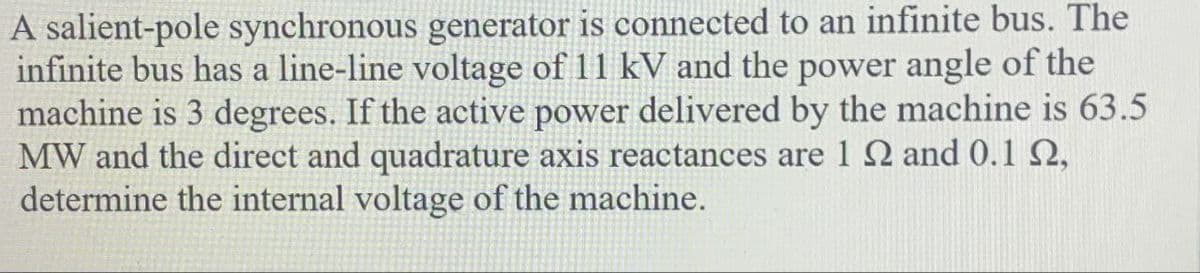
Transcribed Image Text:A salient-pole synchronous generator is connected to an infinite bus. The
infinite bus has a line-line voltage of 11 kV and the power angle of the
machine is 3 degrees. If the active power delivered by the machine is 63.5
MW and the direct and quadrature axis reactances are 1 2 and 0.1 2,
determine the internal voltage of the machine.
Expert Solution
This question has been solved!
Explore an expertly crafted, step-by-step solution for a thorough understanding of key concepts.

Step by step
Solved in 3 steps with 3 images

Knowledge Booster


Learn more about
Need a deep-dive on the concept behind this application? Look no further. Learn more about this topic, electrical-engineering and related others by exploring similar questions and additional content below.Recommended textbooks for you
Power System Analysis and Design (MindTap Course …
Electrical Engineering
ISBN:
9781305632134
Author:
J. Duncan Glover, Thomas Overbye, Mulukutla S. Sarma
Publisher:
Cengage Learning
Power System Analysis and Design (MindTap Course …
Electrical Engineering
ISBN:
9781305632134
Author:
J. Duncan Glover, Thomas Overbye, Mulukutla S. Sarma
Publisher:
Cengage Learning