Task 3 A.C. Series Circuits: 1. R=34.5Ohms L= 322.5mH 0-57.5uF HH AC = 24V, 50Hz Figure 1 Sketch the phasor diagram for the circuit shown in Figure 1, showing: a. The circuit current (I) b. The supply voltage (Vs) C. The volt drop across R (VR) d. The volt drop across L (VL) e. f. The volt drop across C (Vc) The circuit phase angle (D) Assume the circuit to be INDUCTIVE overall.
Task 3 A.C. Series Circuits: 1. R=34.5Ohms L= 322.5mH 0-57.5uF HH AC = 24V, 50Hz Figure 1 Sketch the phasor diagram for the circuit shown in Figure 1, showing: a. The circuit current (I) b. The supply voltage (Vs) C. The volt drop across R (VR) d. The volt drop across L (VL) e. f. The volt drop across C (Vc) The circuit phase angle (D) Assume the circuit to be INDUCTIVE overall.

Delmar's Standard Textbook Of Electricity
7th Edition
ISBN:9781337900348
Author:Stephen L. Herman
Publisher:Stephen L. Herman
Chapter17: Resistive-inductive Series Circuits
Section: Chapter Questions
Problem 1RQ: 1. What is the relationship of voltage and current (concerning phase angle) in a pure resistive...

Related questions

Question
Please answer in typing format
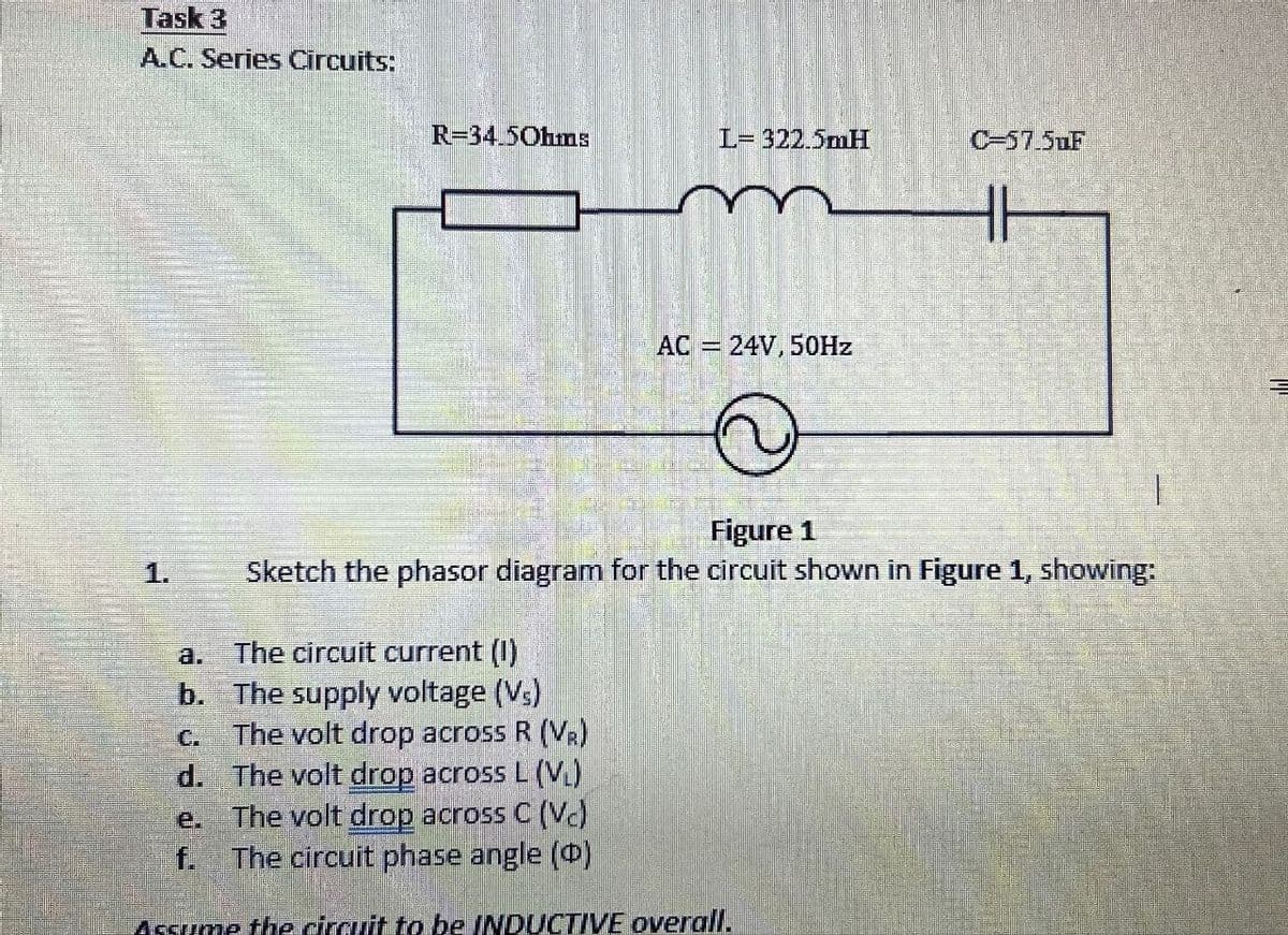
Transcribed Image Text:Task 3
A.C. Series Circuits:
1.
R=34.5Ohms
L= 322.5mH
0-57.5uF
HH
AC = 24V, 50Hz
Figure 1
Sketch the phasor diagram for the circuit shown in Figure 1, showing:
a.
The circuit current (I)
b. The supply voltage (Vs)
C.
The volt drop across R (VR)
d. The volt drop across L (VL)
e.
f.
The volt drop across C (Vc)
The circuit phase angle (D)
Assume the circuit to be INDUCTIVE overall.
Expert Solution
This question has been solved!
Explore an expertly crafted, step-by-step solution for a thorough understanding of key concepts.

Step by step
Solved in 4 steps with 12 images

Knowledge Booster


Learn more about
Need a deep-dive on the concept behind this application? Look no further. Learn more about this topic, electrical-engineering and related others by exploring similar questions and additional content below.Recommended textbooks for you
Delmar's Standard Textbook Of Electricity
Electrical Engineering
ISBN:
9781337900348
Author:
Stephen L. Herman
Publisher:
Cengage Learning
Delmar's Standard Textbook Of Electricity
Electrical Engineering
ISBN:
9781337900348
Author:
Stephen L. Herman
Publisher:
Cengage Learning