A simple power system diagram is given below. The system consists of a 120/0 volt generator connected to an ideal 1:5 step up transformer, a transmission ine, and ideal 10:1 step down transformer and a load. The impedance of the transmission line is 10 + j20, and the impedance of the load is 4+j2 ohms. The base values for the system are chosen to be 120 volts and 10 KVA at the generator. a) Solve for the generator current lg using the per unit system. Do show your calculated per unit diagram. b) Solve for the value of the load voltage from the per unit system circuit. 71 10 n 20n T: 10:1 ZLOAD = 4 + j2 120g load
A simple power system diagram is given below. The system consists of a 120/0 volt generator connected to an ideal 1:5 step up transformer, a transmission ine, and ideal 10:1 step down transformer and a load. The impedance of the transmission line is 10 + j20, and the impedance of the load is 4+j2 ohms. The base values for the system are chosen to be 120 volts and 10 KVA at the generator. a) Solve for the generator current lg using the per unit system. Do show your calculated per unit diagram. b) Solve for the value of the load voltage from the per unit system circuit. 71 10 n 20n T: 10:1 ZLOAD = 4 + j2 120g load

Power System Analysis and Design (MindTap Course List)
6th Edition
ISBN:9781305632134
Author:J. Duncan Glover, Thomas Overbye, Mulukutla S. Sarma
Publisher:J. Duncan Glover, Thomas Overbye, Mulukutla S. Sarma
Chapter12: Power System Controls
Section: Chapter Questions
Problem 12.13P

Related questions

Question
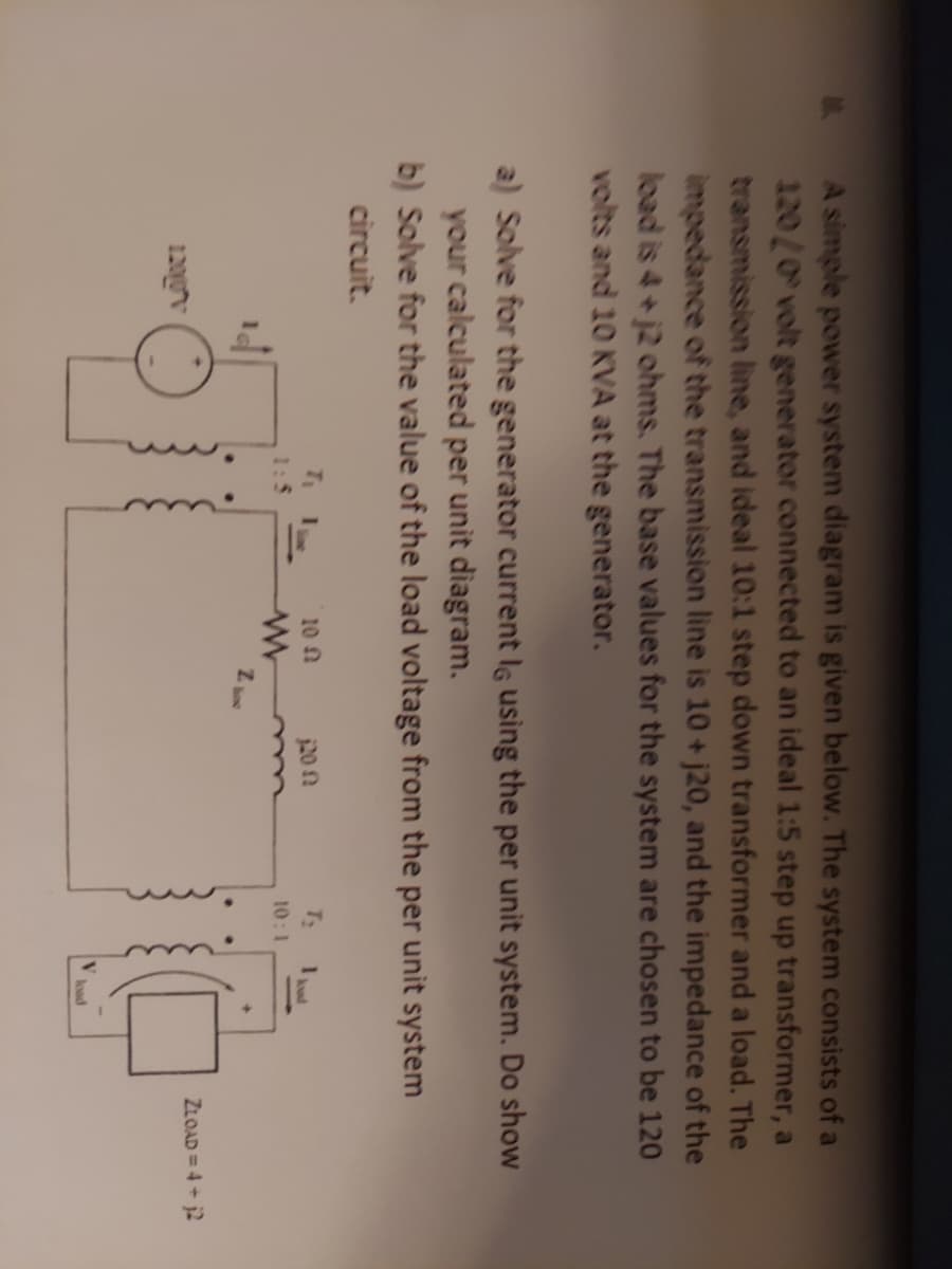
Transcribed Image Text:A simple power system diagram is given below. The system consists of a
120/0 volt generator connected to an ideal 1:5 step up transformer, a
transmission line, and ideal 10:1 step down transformer and a load. The
impedance of the transmission line is 10 + j20, and the impedance of the
load is 4+ j2 ohms. The base values for the system are chosen to be 120
volts and 10 KVA at the generator.
a) Solve for the generator current lg using the per unit system. Do show
your calculated per unit diagram.
b) Solve for the value of the load voltage from the per unit system
circuit.
10 n
20 n
T:
10:1
ZLOAD = 4 + j2
120gv
load
Expert Solution
This question has been solved!
Explore an expertly crafted, step-by-step solution for a thorough understanding of key concepts.

This is a popular solution!

Trending now
This is a popular solution!

Step by step
Solved in 2 steps with 2 images

Knowledge Booster


Learn more about
Need a deep-dive on the concept behind this application? Look no further. Learn more about this topic, electrical-engineering and related others by exploring similar questions and additional content below.Recommended textbooks for you
Power System Analysis and Design (MindTap Course …
Electrical Engineering
ISBN:
9781305632134
Author:
J. Duncan Glover, Thomas Overbye, Mulukutla S. Sarma
Publisher:
Cengage Learning
Power System Analysis and Design (MindTap Course …
Electrical Engineering
ISBN:
9781305632134
Author:
J. Duncan Glover, Thomas Overbye, Mulukutla S. Sarma
Publisher:
Cengage Learning