A single phase half controlled thyristor rectifier deliv- ers a constant load current of 10A at firing angle delay 30°, Average and RMS values of source current are respectively (A) SA, 10A (C) 5A, 9.13A (B) 0A, 9.13A (D) 0A, 10A
A single phase half controlled thyristor rectifier deliv- ers a constant load current of 10A at firing angle delay 30°, Average and RMS values of source current are respectively (A) SA, 10A (C) 5A, 9.13A (B) 0A, 9.13A (D) 0A, 10A

Electricity for Refrigeration, Heating, and Air Conditioning (MindTap Course List)
10th Edition
ISBN:9781337399128
Author:Russell E. Smith
Publisher:Russell E. Smith
Chapter12: Electronic Control Devices
Section: Chapter Questions
Problem 10RQ: Briefly explain the rectification circuit shown in Figure 12.9.

Related questions
Question
text plese else downvote
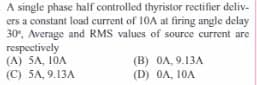
Transcribed Image Text:A single phase half controlled thyristor rectifier deliv-
ers a constant load current of 10A at firing angle delay
30%, Average and RMS values of source current are
respectively
(A) 5A, 10A
(C) 5A, 9.13A
(B) 0A, 9.13A
(D) 0A, 10A
Expert Solution
This question has been solved!
Explore an expertly crafted, step-by-step solution for a thorough understanding of key concepts.

Step by step
Solved in 3 steps with 1 images

Knowledge Booster


Learn more about
Need a deep-dive on the concept behind this application? Look no further. Learn more about this topic, electrical-engineering and related others by exploring similar questions and additional content below.Recommended textbooks for you
Electricity for Refrigeration, Heating, and Air C…
Mechanical Engineering
ISBN:
9781337399128
Author:
Russell E. Smith
Publisher:
Cengage Learning
Electricity for Refrigeration, Heating, and Air C…
Mechanical Engineering
ISBN:
9781337399128
Author:
Russell E. Smith
Publisher:
Cengage Learning