(a) The base impedance in (N) (b) The reactive power drawn by the load (p.u.) (c) The total current (p.u.) drawn from the power supply
(a) The base impedance in (N) (b) The reactive power drawn by the load (p.u.) (c) The total current (p.u.) drawn from the power supply

Power System Analysis and Design (MindTap Course List)
6th Edition
ISBN:9781305632134
Author:J. Duncan Glover, Thomas Overbye, Mulukutla S. Sarma
Publisher:J. Duncan Glover, Thomas Overbye, Mulukutla S. Sarma
Chapter4: Transmission Line Parameters
Section: Chapter Questions
Problem 4.38P

Related questions
Question
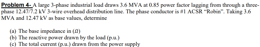
Transcribed Image Text:Problem 4- A large 3-phase industrial load draws 3.6 MVA at 0.85 power factor lagging from through a three-
phase 12.47/7.2 kV 3-wire overhead distribution line. The phase conductor is #1 ACSR “Robin". Taking 3.6
MVA and 12.47 kV as base values, determine
(a) The base impedance in (N)
(b) The reactive power drawn by the load (p.u.)
(c) The total current (p.u.) drawn from the power supply
Expert Solution
This question has been solved!
Explore an expertly crafted, step-by-step solution for a thorough understanding of key concepts.

This is a popular solution!

Trending now
This is a popular solution!

Step by step
Solved in 2 steps with 2 images

Knowledge Booster


Learn more about
Need a deep-dive on the concept behind this application? Look no further. Learn more about this topic, electrical-engineering and related others by exploring similar questions and additional content below.Recommended textbooks for you
Power System Analysis and Design (MindTap Course …
Electrical Engineering
ISBN:
9781305632134
Author:
J. Duncan Glover, Thomas Overbye, Mulukutla S. Sarma
Publisher:
Cengage Learning
Power System Analysis and Design (MindTap Course …
Electrical Engineering
ISBN:
9781305632134
Author:
J. Duncan Glover, Thomas Overbye, Mulukutla S. Sarma
Publisher:
Cengage Learning