A three-phase motor rated for 60 hp, 2200 V, six-pole, 60 Hz squirrel cage induction motor gave the following results under testing. No-load test: f= 60HZ, Line voltage = 2200 V, Line current = 4.5 A, Power = 1600 W Blocked Rotor test: f = 25 HZ, Line voltage = 270 V, Line current = 25 A, Power = 9000 W DC resistance/phase = R1 = 2.8 2 a. Draw the equivalent circuit for the No-Load test and determine corresponding parameters. b. Determine the no-load rotational loss. c. Draw the equivalent circuit for the blocked rotor test and determine the corresponding parameters (assume X1 = X2).
A three-phase motor rated for 60 hp, 2200 V, six-pole, 60 Hz squirrel cage induction motor gave the following results under testing. No-load test: f= 60HZ, Line voltage = 2200 V, Line current = 4.5 A, Power = 1600 W Blocked Rotor test: f = 25 HZ, Line voltage = 270 V, Line current = 25 A, Power = 9000 W DC resistance/phase = R1 = 2.8 2 a. Draw the equivalent circuit for the No-Load test and determine corresponding parameters. b. Determine the no-load rotational loss. c. Draw the equivalent circuit for the blocked rotor test and determine the corresponding parameters (assume X1 = X2).

Introductory Circuit Analysis (13th Edition)
13th Edition
ISBN:9780133923605
Author:Robert L. Boylestad
Publisher:Robert L. Boylestad
Chapter1: Introduction
Section: Chapter Questions
Problem 1P: Visit your local library (at school or home) and describe the extent to which it provides literature...

Related questions

Question
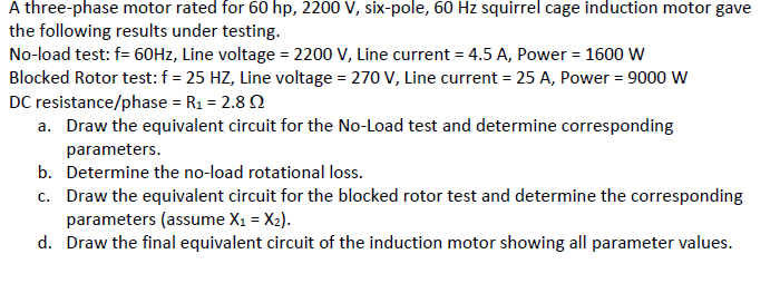
Transcribed Image Text:A three-phase motor rated for 60 hp, 2200 V, six-pole, 60 Hz squirrel cage induction motor gave
the following results under testing.
No-load test: f= 60HZ, Line voltage = 2200 V, Line current = 4.5 A, Power = 1600 W
Blocked Rotor test: f = 25 HZ, Line voltage = 270 V, Line current = 25 A, Power = 9000 W
DC resistance/phase = R1 = 2.8 2
a. Draw the equivalent circuit for the No-Load test and determine corresponding
parameters.
b. Determine the no-load rotational loss.
c. Draw the equivalent circuit for the blocked rotor test and determine the corresponding
parameters (assume X1 = X2).
d. Draw the final equivalent circuit of the induction motor showing all parameter values.
Expert Solution
This question has been solved!
Explore an expertly crafted, step-by-step solution for a thorough understanding of key concepts.

This is a popular solution!

Trending now
This is a popular solution!

Step by step
Solved in 2 steps with 2 images

Knowledge Booster


Learn more about
Need a deep-dive on the concept behind this application? Look no further. Learn more about this topic, electrical-engineering and related others by exploring similar questions and additional content below.Recommended textbooks for you
Introductory Circuit Analysis (13th Edition)
Electrical Engineering
ISBN:
9780133923605
Author:
Robert L. Boylestad
Publisher:
PEARSON

Delmar's Standard Textbook Of Electricity
Electrical Engineering
ISBN:
9781337900348
Author:
Stephen L. Herman
Publisher:
Cengage Learning

Programmable Logic Controllers
Electrical Engineering
ISBN:
9780073373843
Author:
Frank D. Petruzella
Publisher:
McGraw-Hill Education
Introductory Circuit Analysis (13th Edition)
Electrical Engineering
ISBN:
9780133923605
Author:
Robert L. Boylestad
Publisher:
PEARSON
Delmar's Standard Textbook Of Electricity
Electrical Engineering
ISBN:
9781337900348
Author:
Stephen L. Herman
Publisher:
Cengage Learning
Programmable Logic Controllers
Electrical Engineering
ISBN:
9780073373843
Author:
Frank D. Petruzella
Publisher:
McGraw-Hill Education

Fundamentals of Electric Circuits
Electrical Engineering
ISBN:
9780078028229
Author:
Charles K Alexander, Matthew Sadiku
Publisher:
McGraw-Hill Education

Electric Circuits. (11th Edition)
Electrical Engineering
ISBN:
9780134746968
Author:
James W. Nilsson, Susan Riedel
Publisher:
PEARSON

Engineering Electromagnetics
Electrical Engineering
ISBN:
9780078028151
Author:
Hayt, William H. (william Hart), Jr, BUCK, John A.
Publisher:
Mcgraw-hill Education,