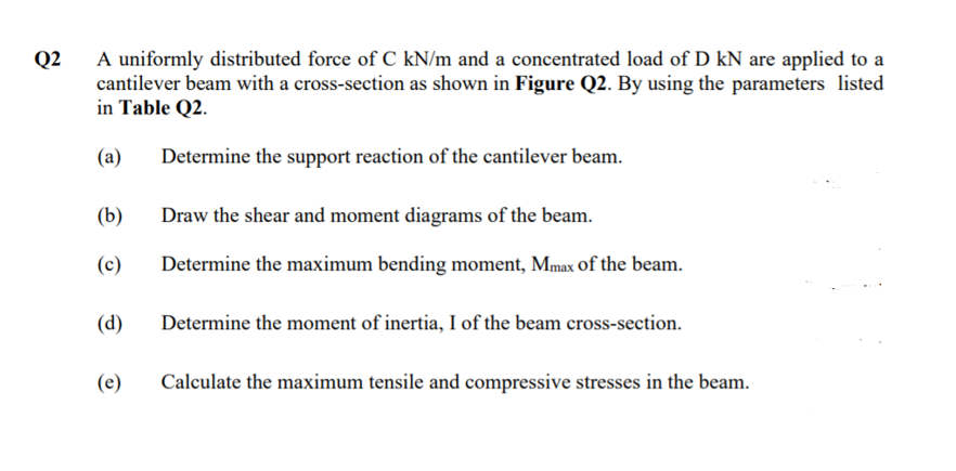
A uniformly distributed force of C kN/m and a concentrated load of D kN are applied to a cantilever beam with a cross-section as shown in Figure Q2. By using the parameters listed in Table Q2.
A uniformly distributed force of C kN/m and a concentrated load of D kN are applied to a cantilever beam with a cross-section as shown in Figure Q2. By using the parameters listed in Table Q2.

Mechanics of Materials (MindTap Course List)
9th Edition
ISBN:9781337093347
Author:Barry J. Goodno, James M. Gere
Publisher:Barry J. Goodno, James M. Gere
Chapter4: Shear Forces And Bending Moments
Section: Chapter Questions
Problem 4.3.8P: At a full d raw, an archer applies a pull of 130 N to the bowstring of the bow shown in the figure....

Related questions
Question
answer quickly
Transcribed Image Text:A uniformly distributed force of C kN/m and a concentrated load of D kN are applied to a
cantilever beam with a cross-section as shown in Figure Q2. By using the parameters listed
in Table Q2.
Q2
(a)
Determine the support reaction of the cantilever beam.
(b)
Draw the shear and moment diagrams of the beam.
(c)
Determine the maximum bending moment, Mmax of the beam.
(d)
Determine the moment of inertia, I of the beam cross-section.
(e)
Calculate the maximum tensile and compressive stresses in the beam.
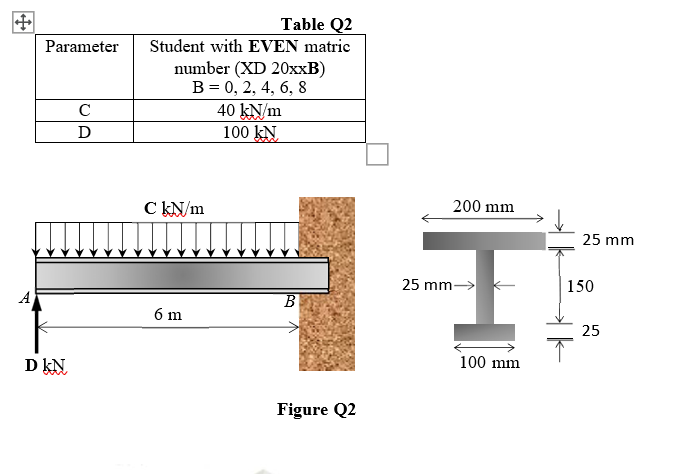
Transcribed Image Text:Table Q2
Parameter
Student with EVEN matric
number (XD 20XXB)
B = 0, 2, 4, 6, 8
40 kN/m
100 kN.
C
D
C KN/m
200 mm
25 mm
25 mm> k
150
A
6 m
25
D kN.
100 mm
Figure Q2
Expert Solution
This question has been solved!
Explore an expertly crafted, step-by-step solution for a thorough understanding of key concepts.

Step by step
Solved in 2 steps with 2 images

Knowledge Booster


Learn more about
Need a deep-dive on the concept behind this application? Look no further. Learn more about this topic, mechanical-engineering and related others by exploring similar questions and additional content below.Recommended textbooks for you
Mechanics of Materials (MindTap Course List)
Mechanical Engineering
ISBN:
9781337093347
Author:
Barry J. Goodno, James M. Gere
Publisher:
Cengage Learning
Mechanics of Materials (MindTap Course List)
Mechanical Engineering
ISBN:
9781337093347
Author:
Barry J. Goodno, James M. Gere
Publisher:
Cengage Learning