cross-section, simply supported at locations A and C. A uniformly distributed load of 10 kN/m is applied on the part AB of the beam together with a concentrated load of 20 kN at the end D. 10kN/m 20kN AV 4m 4m 2m Fig.Q2: Structural Beam (a) Draw a free body diagram and find the reaction forces at the supports A and C. (b) Draw the shear force diagram (SFD) for the beam and show the values at A, B, C and D. (c) Draw the bending moment diagram (BMD) and show the values at A, B, C and D.
cross-section, simply supported at locations A and C. A uniformly distributed load of 10 kN/m is applied on the part AB of the beam together with a concentrated load of 20 kN at the end D. 10kN/m 20kN AV 4m 4m 2m Fig.Q2: Structural Beam (a) Draw a free body diagram and find the reaction forces at the supports A and C. (b) Draw the shear force diagram (SFD) for the beam and show the values at A, B, C and D. (c) Draw the bending moment diagram (BMD) and show the values at A, B, C and D.

Mechanics of Materials (MindTap Course List)
9th Edition
ISBN:9781337093347
Author:Barry J. Goodno, James M. Gere
Publisher:Barry J. Goodno, James M. Gere
Chapter10: Statically Indeterminate Beams
Section: Chapter Questions
Problem 10.4.14P: A propped cantilever beam of a length 2L is loaded by a uniformly distributed load with intensity q....

Related questions

Question
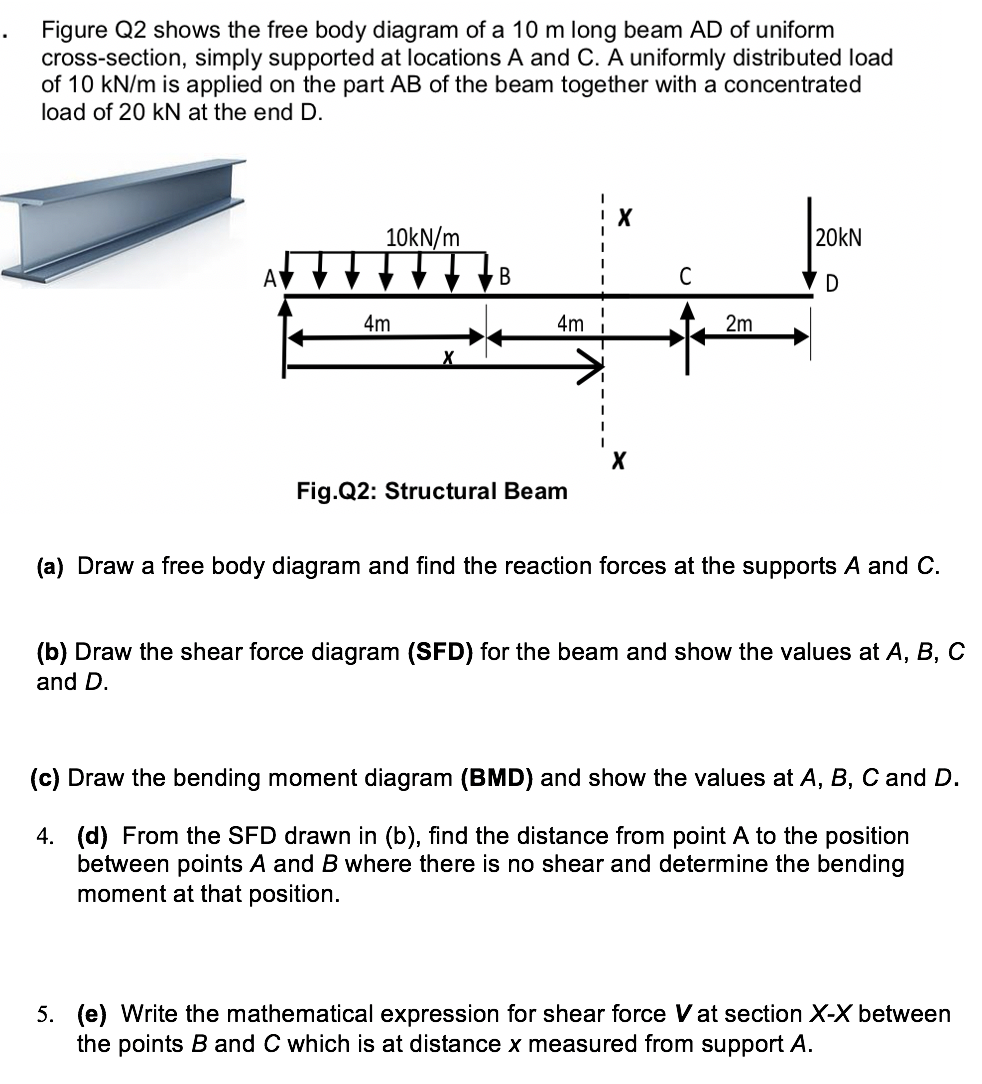
Transcribed Image Text:Figure Q2 shows the free body diagram of a 10 m long beam AD of uniform
cross-section, simply supported at locations A and C. A uniformly distributed load
of 10 kN/m is applied on the part AB of the beam together with a concentrated
load of 20 kN at the end D.
10KN/m
20kN
4m
4m
2m
X
Fig.Q2: Structural Beam
(a) Draw a free body diagram and find the reaction forces at the supports A and C.
(b) Draw the shear force diagram (SFD) for the beam and show the values at A, B, C
and D.
(c) Draw the bending moment diagram (BMD) and show the values at A, B, C and D.
4. (d) From the SFD drawn in (b), find the distance from point A to the position
between points A and B where there is no shear and determine the bending
moment at that position.
5. (e) Write the mathematical expression for shear force V at section X-X between
the points B and C which is at distance x measured from support A.
Expert Solution
This question has been solved!
Explore an expertly crafted, step-by-step solution for a thorough understanding of key concepts.

Step by step
Solved in 3 steps with 1 images

Knowledge Booster


Learn more about
Need a deep-dive on the concept behind this application? Look no further. Learn more about this topic, mechanical-engineering and related others by exploring similar questions and additional content below.Recommended textbooks for you
Mechanics of Materials (MindTap Course List)
Mechanical Engineering
ISBN:
9781337093347
Author:
Barry J. Goodno, James M. Gere
Publisher:
Cengage Learning
Mechanics of Materials (MindTap Course List)
Mechanical Engineering
ISBN:
9781337093347
Author:
Barry J. Goodno, James M. Gere
Publisher:
Cengage Learning