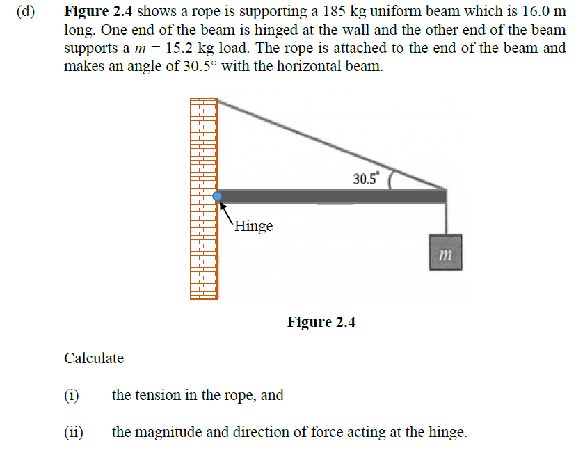
Figure 2.4 shows a rope is supporting a 185 kg uniform beam which is 16.0 m long. One end of the beam is hinged at the wall and the other end of the beam supports a m = 15.2 kg load. The rope is attached to the end of the beam and makes an angle of 30.5° with the horizontal beam. (d) 30.5° `Hinge m Figure 2.4 Calculate (i) the tension in the rope, and (ii) the magnitude and direction of force acting at the hinge.
Q: A uniformly distributed force of C kN/m and a concentrated load of D kN are applied to a cantilever…
A:
Q: Eight steel cables (with equal distance to each other) are supporting a circular heavy moulding of…
A: As it is not mentioned that which three parts need to be solved, please find solutions of first…
Q: A uniform, 7.5-m-long beam weighing 6490 N is hinged to a wall and supported by a thin cable…
A: The given system is shown below, OA=7.5 m,Weight of the beam, W=6490 N,AB=1.5 m. Drawing the FBD of…
Q: The lamp shown in the figure is supported by a pole AO and cables AC and AB. Each cable can sustain…
A:
Q: Example 18. The homogeneous bar AB of 300 N is resting as shown in figure Ex.18. Assuming contact…
A:
Q: 4 m F, E F, 4 m B F F, 4 m G 4 m
A:
Q: QI A uniform 500 N beam supports a 700 N load as shown in Figure Q1. Calculate the tension in the…
A: Given Data Weight of the beam is: w=500 N Weight of the load is: W=700 N Angle made at the top rope…
Q: Two loads 400N and 500N are suspended in a vertical plane by three springs as shown in Figure. Find…
A:
Q: What would be the maximum weight W of the block, shown in the following figure, so that the tension…
A:
Q: round bar of length L. modulus of elasticity E, and weight density tapers uniformly from a diameter…
A: Given:Length of round bar=L,Modulus of elasticity= E,Weight density=γ,Diameter at one end=3DDiameter…
Q: The axially loaded bar ABCD shown in figure 2 is held between 2 rigid supports. The bar has…
A: The free-body diagram of the given axial bar can be drawn as below, Here, RA and RD are the…
Q: 1. A beam 3 m long weighing 400 N is suspended in a horizontal position by two vertical strings,…
A: Given data Length = 3m Weight of beam = 400N Maximum tension = 350N Body weight = 200N
Q: A steel cable with nominal diameter 25 mm as shown in Table Q2(a) is used in a construction yard to…
A:
Q: For figure below, the tension in the * cable is 0.25 m A 25° B 0.5 m - 0.12 m 1.5 m 14 &N
A:
Q: can be in different positions “x” on the wall. The cable that secures the end of the bar to the…
A:
Q: A 4.20 m long (L) steel pipe has a mass of 450 kg and is lifted by a crane attached to cable CD.…
A:
Q: Q2 (a) A steel cable with nominal diameter 25 mm as shown in Table Q2(a) is used in a construction…
A:
Q: A cable whose length is 16m and sag of 2m supports a weight of 1500 N/m. What is the minimum tension…
A:
Q: A girder shown in the following figure is supported by two cables. The weight of the girder is 8000…
A: For the given girder Weight of girder (W) = 8000 lb To determine The tension in both cable and…
Q: Example 2.4. A machine component 1.5 m long and weight 1000 N is supported by two ropes AB and CD as…
A: Given:-L=1.5mW=1000 Nθ1=60°θ2=45°To find:-Tensions in the ropes AB and CDT1 and T2
Q: A flanged wooden shape is used to support the loads shown on the beam. The dimensions of the shape…
A:
Q: Figure 6: 5 m/ 5 m 5 m B 20 KN A simple truss is subjected to 20 KN force at the point A as shown in…
A: The reaction force at point C is 20 kN (Tension). Therefore, option (b) is correct answer.
Q: 800 N-m 2 m .8 m 3 m .4 m .2 m Figure P.5.29. 5.30. Find the supporting force systems at A and B.…
A: Since you have asked multiple questions, only the first question is solved for you. If you want any…
Q: A 15,000 N crane pivots around a friction-free axle at its base and is supported by a cable making a…
A: a.
Q: A 400 N gas sign hangs from the end of a uniform strut BC. The strut is 4 m long and weighs 600 N.…
A: FBD of given figure First we calculate the angle tanθ=34θ=tan-134θ=36.86 Now consider clockwise…
Q: For figure below, the tension in the cable is 0.25 m 25° В 0.5 m 0.12 m 1.5 m 14. «N 5 m
A:
Q: A weightless rectangular bar BDC is loaded as shown below. There is a smooth pin at point C, a 100 N…
A: Part A) Draw the polar vector form as follows.
Q: For the cantilever truss in Figure, determine the force in each member. | 100 N 60 30 5m 10 m 1000 N…
A: For the given truss To determine forces in each member
Q: An unknown weight falls by 30 mm onto a collar rigidly attached to the lower end of a vertical bar 4…
A:
Q: What would be the maximum weight W of the block, shown in the following figure, so that the tension…
A:
Q: A homogeneous 1.5 kN bar AB carries a 2 kN force as shown in the figure. The bar is supported by a…
A:
Q: Example 4.2. A beam 3 m long weighing 400 N is suspended in a horizontal position by two vertical…
A: Given data: Length of the beam (L) = 3 m Weight of the beam = 400 N Weight of the body = 200 N Need…
Q: A 1480-N uniform beam is attached to a vertical wall at one end and is supported by a cable at the…
A:
Q: m
A: Given Data: The mass of the block is M= 27 kg. The mass of the beam is m = 7.7 kg. The free-body…
Q: he Figure shows a bar AB, of length L, which is supported at point A, against the wall and suspended…
A:
Q: k2 2 13 ki P Rigid bar k3 3 for the system shown in the figure, which of the following statements…
A: The rigid bar of system is given The displacement of rigid bar is given as, u The load acting on…
Q: 4. A uniform 45-kg beam is held in a vertical position by a pin at its lower end and a cable at its…
A:
Q: 2. In the figure below, the cable BCD passes over a smooth pulley and is attached to a ring at E and…
A: givenmaximum tension in any cable cannot exceed 10kNpulley weight arrangement
Q: The cable shown in Fig. distributed load of 25 kN per meter of horizontal length. The left support…
A: Given: uniform distributed load w=25 kN/m Height of the distance between supports, h = 50 m angle,…
Q: 1. A beam 3 m long weighing 400 N is suspended in a horizontal position by two vertical strings,…
A:
Q: An electric pole design is shown below. The frame is used to carry high-voltage wires. If b=600 mm,…
A:
Q: As shown, beam ABC is supported by the roller at A and pin at C. The geometry of the beam is given…
A:
Q: A uniform tubular pipe 100ft long and weighing 55lbs is supported by a fulcrum as shown in the…
A:
Q: e prismatic bar AC is supported by a hinge at C and cable ADB that runs through a frictionless…
A:
Q: A ladder 12 m long leans against a vertical frictionless wall with its lower end 3 m from the wall.…
A: Hello. Since you have posted multiple questions and not specified which question needs to be solved,…
Q: A simple truss is subjected to 20 kN force at point A as shown in Figure 2. The reaction force at…
A:
Q: wood-stave penstock of 1.8 m diameter is wrapped with steel hoops and subjected to a fluid pressure…
A:
Q: ven m-50kg and the following dimensions: AB = 1m, BC 3m, angle ACD 30 degrees Draw a free body…
A:
Step by step
Solved in 2 steps with 2 images
- An L-shaped reinforced concrete slab 12 Ft X 12 ft, with a 6 Ft X 6 ft cut-out and thickness t = 9.0 in, is lifted by three cables attached at O, B, and D, as shown in the figure. The cables are are combined at point Q, which is 7.0 Ft above the top of the slab and directly above the center of mass at C. Each cable has an effective cross-sectional area of Ae= 0.12 in2. (a) Find the tensile force Tr(i = 1, 2, 3) in each cable due to the weight W of the concrete slab (ignore weight of cables). (b) Find the average stress ov in each cable. (See Table I-1 in Appendix I for the weight density of reinforced concrete.) (c) Add cable AQ so that OQA is one continuous cable, with each segment having Force T, which is connected to cables BQ and DQ at point Q. Repeat parts (a) and (b). Hini: There are now three Forced equilibrium equations and one constrain equation, T1= T4.A steel riser pipe hangs from a drill rig located offshore in deep water (see figure). (a) What is the greatest length (meters) it can have without breaking if the pipe is suspended in the air and the ultimate strength (or breaking strength) is 550 MPa? (b) If the same riser pipe hangs from a drill rig at sea, what is the greatest length? (Obtain the weight densities of steel and sea water from Table M, Appendix I. Neglect the effect of buoyant foam casings on the pipe.)A space truss is restrained at joints O, A. B. and C, as shown in the figure. Load P is applied at joint A and load IP acts downward at joint C. (a) Find reaction force components Ax, By, and B. in terms of load variable P. (b) Find the axial force in truss member AB in terms of load variable P.
- Space frame A BCD is clamped at A, except it is Free to translate in the .v direction. There is also a roller support at D, which is normal to line CDE. A triangularly distributed Force with peak intensity q0 = 75 N/m acts along AB in the positive - direction. Forces Px= 60 N and Pz = = 45 N are applied at joint C, and a concentrated moment My = 120 N . m acts at the mid-span of member BC. (a) Find reactions at supports A and I). (b) Find internal stress resultants N. E’I T, and .11 at the mid-height of segment AB..15 A hitch-mounted bicycle rack is designed to carry up to four 30-lb bikes mounted on and strapped to two arms Gil (sec bike loads in the figure part a) The rack is attached to the vehicle at A and is assumed to be like a cant silkier beam A BCDGII (figure part b) The light of fixed segment AB is U = 10 lb. centered 9 in. from A (see figure part b) and the rest of the rack highs W2 = 40 lb. centered 19 in. from A. Segment ABCDG is a steel tube o(2 X 2 in. with a thickness I = 118 in. Segment BCDGII pivots about a bolt at B with a diameter d1 = 0.25 in. to allow access to the rear of the vehicle without removing the hitch rack. When in use, the rack is secured in an upright posit ion by a pin C(diameter o( pin d, = 5116 in.) (see phoo and figure part C). The of returning effect of the bikes on the rack is resisted by a force couple F h at BC. (a) Find the support reactions at A for the fully loaded rack. (b) Find forces in the bolt at B and the pin at C. (c) Find average shear stresses in both the bolt at Band the pin at C. (d) Find average bearing stresses o, in the bolt at B and the pin at C.A large precast concrete panel for a warehouse is raised using two sets of cables at two lift lines, as shown in the figure part a. Cable 1 has a length L1 = 22 Ft, cable 2 has a length L2= 10 ft, and the distance along the panel between lift points Band D is d = 14 ft (see figure part b). The total weight of the panel is W = 85 kips. Assuming the cable lift Forces F at each lift line are about equal, use the simplified model of one half of the panel in figure part b to perform your analysis for the lift position shown. Find the required cross-sectional area AC of the cable if its breaking stress is 91 ksi and a factor of safety of 4 with respect to failure is desired.
- *16 A prismatic bar AB of length L, cross-sectional area A, modulus of elasticity E, and weight Changs vertically under its own weight (see figure). (a) Derive a formula for the downward displacement Scof point E. located at distance It from the lower end of the bar. (b) What is the elongation SBof the entire bar? (c) What is the ratio £ of the elongation, of the upper half of the bar to the elongation of the lower half of the bar? (d) If bar A B is a riser pipe hanging from a drill rig at sea. what is the total elongation of the pipe? Let L = 1500 m, A - 0.ol57 m2, and E = 210 GPa. See Appendix 1 for weight densities of steel and sea water. (See Probs. 1.4-2 and J.7-13 for additional figures.)A hollow circular pipe (see figure} support s a load P that is uniformly distributed around a cap plate at the top of the lower pipe. The inner and outer diameters of the upper and lower parts of the pipe are d1= 50 mm, d2= 60 mm, rf3 = 57 mm, and d1= 64 mm, respectively. Pipe lengths are Lt= 2 m and L, = 3 m. Neglect the self-weight of the pipes. Assume that cap plate thickness is small compared to I, and E,. Let E = 110 MPa. (a) If the tensile stress in the upper part is d = 10.5 MPa. what is load PI Also, what are reactions ft, at the upper support and R-, at the lower support? What is the stress ar(MPa) in the lower part? (b) Find displacement S(mm) at the cap plate. Plot the axial force diagram (AFD) [Ar(.f)] and axial displacement diagram (ADD)[5(.t)]. (c) Add the uniformly distributed load q along the censorial axis of pipe segment 2. Find q (kN/m) so that It, = 0. Assume that load P from part (a) is also applied.A soccer goal is subjected to gravity loads (in the - z direction, w = 73 N/m for DG, BG, and BC; w = 29 N/m for all other members; see figure) and a force F = 200 N applied eccentrically at the mid-height of member DG. Find reactions at sup ports C, D, and H.
- Two pipe columns (AB, FC) are pin-connected to a rigid beam (BCD), as shown in the figure. Each pipe column has a modulus of E, but heights (L1or L2) and outer diameters (d1or different for each column. Assume the inner diameter of each column is 3/4 of outer diameter. Uniformly distributed downward load q = 2PIL is applied over a distance of 3L/4 along BC, and concentrated load PIA is applied downward at D. (a) Derive a formula for the displacementSolve the preceding problem for the following data: b = 8.0 in., k = 16 lb/in., a = 45°, and P = 10 lb.A long re Lai nine: wall is braced by wood shores set at an angle of 30° and supported by concrete thrust blocks, as shown in the first part of the figure. The shores are evenly spaced at 3 m apart. For analysis purposes, the wall and shores are idealized as shown in the second part of the figure. Note that the base of the wall and both ends of the shores are assumed to be pinned. The pressure of the soil against the wall is assumed to be triangularly distributed, and the resultant force acting on a 3-meter length of the walls is F = 190 kN. If each shore has a 150 mm X 150 mm square cross section, what is the compressive stress