a. Determine the bias current, /BIAS, given that the input currents to an op- amp are and 7,9 mA, 8.3 mA. b. Compare a practical op-amp to an ideal op-amp. c. Determine the input and output impedances for amplifier configuration in Figure 2.
a. Determine the bias current, /BIAS, given that the input currents to an op- amp are and 7,9 mA, 8.3 mA. b. Compare a practical op-amp to an ideal op-amp. c. Determine the input and output impedances for amplifier configuration in Figure 2.

Delmar's Standard Textbook Of Electricity
7th Edition
ISBN:9781337900348
Author:Stephen L. Herman
Publisher:Stephen L. Herman
Chapter18: Resistive-inductive Parallel Circuits
Section: Chapter Questions
Problem 13PP: In an R-L parallel circuit, IT=1.25 amps, R=1.2k, and XL=1k. Find IR

Related questions
Question
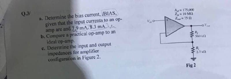
Transcribed Image Text:Q.3/
a. Determine the bias current, /BIAS,
given that the input currents to an op-
amp are and 7,9 mA, 8.3 mA.
b. Compare a practical op-amp to an
ideal op-amp.
c. Determine the input and output
impedances for amplifier
configuration in Figure 2.
A- 175,000
Z- 10 M)
Z= 75 0
S60 Kn
R,
2.7 k
Fig 2
Expert Solution
This question has been solved!
Explore an expertly crafted, step-by-step solution for a thorough understanding of key concepts.

Step by step
Solved in 5 steps with 1 images

Knowledge Booster


Learn more about
Need a deep-dive on the concept behind this application? Look no further. Learn more about this topic, electrical-engineering and related others by exploring similar questions and additional content below.Recommended textbooks for you
Delmar's Standard Textbook Of Electricity
Electrical Engineering
ISBN:
9781337900348
Author:
Stephen L. Herman
Publisher:
Cengage Learning
Delmar's Standard Textbook Of Electricity
Electrical Engineering
ISBN:
9781337900348
Author:
Stephen L. Herman
Publisher:
Cengage Learning