a. Find the Thévenin equivalent circuit for the network external to the resistor R in Figure. b. Find the current through R when R is 202, 3002, and 100. R₁ R3 w W 60 40 E18 V R₁ 30
a. Find the Thévenin equivalent circuit for the network external to the resistor R in Figure. b. Find the current through R when R is 202, 3002, and 100. R₁ R3 w W 60 40 E18 V R₁ 30

Delmar's Standard Textbook Of Electricity
7th Edition
ISBN:9781337900348
Author:Stephen L. Herman
Publisher:Stephen L. Herman
Chapter18: Resistive-inductive Parallel Circuits
Section: Chapter Questions
Problem 12PP: In an R-L parallel circuit, ET=480 volts, R=16, and XL=24. Find PF.

Related questions
Question
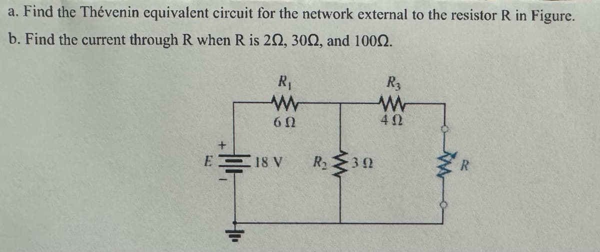
Transcribed Image Text:a. Find the Thévenin equivalent circuit for the network external to the resistor R in Figure.
b. Find the current through R when R is 202, 3002, and 100.
R₁
R3
w
W
60
40
E18 V
R₁
30
Expert Solution
This question has been solved!
Explore an expertly crafted, step-by-step solution for a thorough understanding of key concepts.

This is a popular solution!

Trending now
This is a popular solution!

Step by step
Solved in 2 steps with 3 images

Recommended textbooks for you
Delmar's Standard Textbook Of Electricity
Electrical Engineering
ISBN:
9781337900348
Author:
Stephen L. Herman
Publisher:
Cengage Learning
Delmar's Standard Textbook Of Electricity
Electrical Engineering
ISBN:
9781337900348
Author:
Stephen L. Herman
Publisher:
Cengage Learning