a.1) In a certain UJT, r'B1 = 2.5 k and r'B2 = 4 KQ. What is the intrinsic standoff ratio? a.2) Determine the peak-point voltage for the UJT in problem a.1 if VBB = 15 V. a.3) Find the range of values of R₁ in Figure 2-10 that will ensure proper turn-on and tum-off of the UJT. n = 0.68, Vv = 0.8 V, v = 15 mA, Ip = 10 μA, and Vp = 10 V.
a.1) In a certain UJT, r'B1 = 2.5 k and r'B2 = 4 KQ. What is the intrinsic standoff ratio? a.2) Determine the peak-point voltage for the UJT in problem a.1 if VBB = 15 V. a.3) Find the range of values of R₁ in Figure 2-10 that will ensure proper turn-on and tum-off of the UJT. n = 0.68, Vv = 0.8 V, v = 15 mA, Ip = 10 μA, and Vp = 10 V.

Introductory Circuit Analysis (13th Edition)
13th Edition
ISBN:9780133923605
Author:Robert L. Boylestad
Publisher:Robert L. Boylestad
Chapter1: Introduction
Section: Chapter Questions
Problem 1P: Visit your local library (at school or home) and describe the extent to which it provides literature...

Related questions
Question
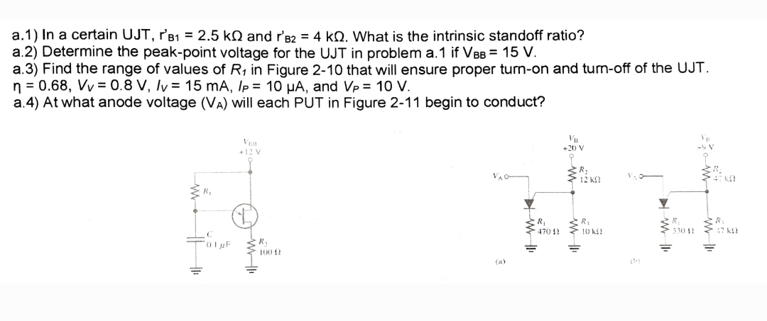
Transcribed Image Text:a.1) In a certain UJT, r'B₁ = 2.5 k and r'B2 = 4 k. What is the intrinsic standoff ratio?
a.2) Determine the peak-point voltage for the UJT in problem a.1 if VBB = 15 V.
a.3) Find the range of values of R₁ in Figure 2-10 that will ensure proper turn-on and turn-off of the UJT.
n = 0.68, Vv = 0.8 V, /v = 15 mA, Ip = 10 μA, and Vp = 10 V.
a.4) At what anode voltage (VA) will each PUT in Figure 2-11 begin to conduct?
+12 V
£₂
0.1 μF
H10
R₁
100 (2
VB
+20 V
R₂
12 KO
R₁
R₁
470 42 10 k
330 42
=
47 k
Expert Solution
This question has been solved!
Explore an expertly crafted, step-by-step solution for a thorough understanding of key concepts.

Step by step
Solved in 2 steps with 2 images

Knowledge Booster


Learn more about
Need a deep-dive on the concept behind this application? Look no further. Learn more about this topic, electrical-engineering and related others by exploring similar questions and additional content below.Recommended textbooks for you
Introductory Circuit Analysis (13th Edition)
Electrical Engineering
ISBN:
9780133923605
Author:
Robert L. Boylestad
Publisher:
PEARSON

Delmar's Standard Textbook Of Electricity
Electrical Engineering
ISBN:
9781337900348
Author:
Stephen L. Herman
Publisher:
Cengage Learning

Programmable Logic Controllers
Electrical Engineering
ISBN:
9780073373843
Author:
Frank D. Petruzella
Publisher:
McGraw-Hill Education
Introductory Circuit Analysis (13th Edition)
Electrical Engineering
ISBN:
9780133923605
Author:
Robert L. Boylestad
Publisher:
PEARSON
Delmar's Standard Textbook Of Electricity
Electrical Engineering
ISBN:
9781337900348
Author:
Stephen L. Herman
Publisher:
Cengage Learning
Programmable Logic Controllers
Electrical Engineering
ISBN:
9780073373843
Author:
Frank D. Petruzella
Publisher:
McGraw-Hill Education

Fundamentals of Electric Circuits
Electrical Engineering
ISBN:
9780078028229
Author:
Charles K Alexander, Matthew Sadiku
Publisher:
McGraw-Hill Education

Electric Circuits. (11th Edition)
Electrical Engineering
ISBN:
9780134746968
Author:
James W. Nilsson, Susan Riedel
Publisher:
PEARSON

Engineering Electromagnetics
Electrical Engineering
ISBN:
9780078028151
Author:
Hayt, William H. (william Hart), Jr, BUCK, John A.
Publisher:
Mcgraw-hill Education,