A2 a) Design a common emitter amplifier as shown in Figure A2, with a split emitter resistor to control the gain. The specification of the amplifier is as listed below, and 10 base currents method can be used for the design. Fixed parameters: Where VCC=7.2V, VE=VCC/3, VBE=0.7V, Beta = 160, RL = 75kOhms Specification: Design for Max Symmetrical Swing, IC = 0.7mA, AV = 30DB i) Sketch the DC voltages and superimpose the AC voltages on the same sketch to highlight your understanding of the design. i) Determine the value of RE and RC. i) Determine the values of RU and RL for the design iv) Determine the bias components RE1 and RE2 for the design b) Determine the input impedance of the transistor amplifier using the small signal equivalent model for the circuit above. i) Sketch the small signal model. i) Calculate the value of the input impedance. Evaluate the influence of the coupling capacitor and the equivalent input impedance if they serve as a filter. Vout 1u BLOAD 75k REI VOFF =0 VAMPL= 10m FREQ = 1000 AC= 10m RE 10u Figure A2 Common Emitter Amplifier design 8 la
A2 a) Design a common emitter amplifier as shown in Figure A2, with a split emitter resistor to control the gain. The specification of the amplifier is as listed below, and 10 base currents method can be used for the design. Fixed parameters: Where VCC=7.2V, VE=VCC/3, VBE=0.7V, Beta = 160, RL = 75kOhms Specification: Design for Max Symmetrical Swing, IC = 0.7mA, AV = 30DB i) Sketch the DC voltages and superimpose the AC voltages on the same sketch to highlight your understanding of the design. i) Determine the value of RE and RC. i) Determine the values of RU and RL for the design iv) Determine the bias components RE1 and RE2 for the design b) Determine the input impedance of the transistor amplifier using the small signal equivalent model for the circuit above. i) Sketch the small signal model. i) Calculate the value of the input impedance. Evaluate the influence of the coupling capacitor and the equivalent input impedance if they serve as a filter. Vout 1u BLOAD 75k REI VOFF =0 VAMPL= 10m FREQ = 1000 AC= 10m RE 10u Figure A2 Common Emitter Amplifier design 8 la

Introductory Circuit Analysis (13th Edition)
13th Edition
ISBN:9780133923605
Author:Robert L. Boylestad
Publisher:Robert L. Boylestad
Chapter1: Introduction
Section: Chapter Questions
Problem 1P: Visit your local library (at school or home) and describe the extent to which it provides literature...

Related questions
Question
Do both A and B
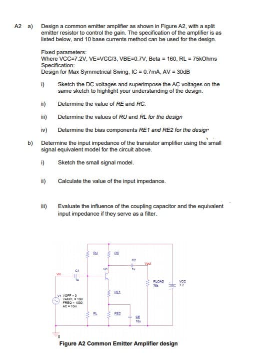
Transcribed Image Text:A2 a) Design a common emitter amplifier as shown in Figure A2, with a split
emitter resistor to control the gain. The specification of the amplifier is as
listed below, and 10 base currents method can be used for the design.
Fixed parameters:
Where VCC=7.2V, VE=VCC/3, VBE=0.7v, Beta = 160, RL = 75kOhms
Specification:
Design for Max Symmetrical Swing, IC = 0.7mA, AV = 30DB
i)
Sketch the DC voltages and superimpose the AC voltages on the
same sketch to highlight your understanding of the design.
ii)
Determine the value of RE and RC.
i)
Determine the values of RU and RL for the design
iv)
Determine the bias components RE1 and RE2 for the design
b) Determine the input impedance of the transistor amplifier using the small
signal equivalent model for the circuit above.
i)
Sketch the small signal model.
ii)
Calculate the value of the input impedance.
iii)
Evaluate the influence of the coupling capacitor and the equivalent
input impedance if they serve as a filter.
BU
RC
C2
Vout
Q1
tu
C1
Vin
1u
BLOAD
75k
RE1
VI VOFF0
VAMPL = 10m
FREQ = 1000
AC= 10m
RE2
CE
10u
Figure A2 Common Emitter Amplifier design
Expert Solution
This question has been solved!
Explore an expertly crafted, step-by-step solution for a thorough understanding of key concepts.

Step by step
Solved in 5 steps with 4 images

Knowledge Booster

![Digital Modulation Scheme (Amplitude-Shift Keying [ASK], Phase-Shift Keying [PSK], Frequency-Shift Keying [FSK])](/static/compass_v2/subjects/engineering/electrical-engineering.svg)
Learn more about
Need a deep-dive on the concept behind this application? Look no further. Learn more about this topic, electrical-engineering and related others by exploring similar questions and additional content below.Recommended textbooks for you
Introductory Circuit Analysis (13th Edition)
Electrical Engineering
ISBN:
9780133923605
Author:
Robert L. Boylestad
Publisher:
PEARSON

Delmar's Standard Textbook Of Electricity
Electrical Engineering
ISBN:
9781337900348
Author:
Stephen L. Herman
Publisher:
Cengage Learning

Programmable Logic Controllers
Electrical Engineering
ISBN:
9780073373843
Author:
Frank D. Petruzella
Publisher:
McGraw-Hill Education
Introductory Circuit Analysis (13th Edition)
Electrical Engineering
ISBN:
9780133923605
Author:
Robert L. Boylestad
Publisher:
PEARSON
Delmar's Standard Textbook Of Electricity
Electrical Engineering
ISBN:
9781337900348
Author:
Stephen L. Herman
Publisher:
Cengage Learning
Programmable Logic Controllers
Electrical Engineering
ISBN:
9780073373843
Author:
Frank D. Petruzella
Publisher:
McGraw-Hill Education

Fundamentals of Electric Circuits
Electrical Engineering
ISBN:
9780078028229
Author:
Charles K Alexander, Matthew Sadiku
Publisher:
McGraw-Hill Education

Electric Circuits. (11th Edition)
Electrical Engineering
ISBN:
9780134746968
Author:
James W. Nilsson, Susan Riedel
Publisher:
PEARSON

Engineering Electromagnetics
Electrical Engineering
ISBN:
9780078028151
Author:
Hayt, William H. (william Hart), Jr, BUCK, John A.
Publisher:
Mcgraw-hill Education,