Q-1-a) From the circuit in the Figure-1, determine the DC-bias operation Parameters: (i) IB (ii) Ic (iii) le (iv) VBE (v) VB (vi) Vc (vii) VCE (viii) Ve (Figure-1) Re RB= 380kN,Rc= 1kN B = 100, VBB = Vcc=12V RB ВЕ BB Q-1-b) Describe briefly the input / output characteristics and application of Common Emitter BJT Configuration ww
Q-1-a) From the circuit in the Figure-1, determine the DC-bias operation Parameters: (i) IB (ii) Ic (iii) le (iv) VBE (v) VB (vi) Vc (vii) VCE (viii) Ve (Figure-1) Re RB= 380kN,Rc= 1kN B = 100, VBB = Vcc=12V RB ВЕ BB Q-1-b) Describe briefly the input / output characteristics and application of Common Emitter BJT Configuration ww

Power System Analysis and Design (MindTap Course List)
6th Edition
ISBN:9781305632134
Author:J. Duncan Glover, Thomas Overbye, Mulukutla S. Sarma
Publisher:J. Duncan Glover, Thomas Overbye, Mulukutla S. Sarma
Chapter12: Power System Controls
Section: Chapter Questions
Problem 12.4P

Related questions

Question
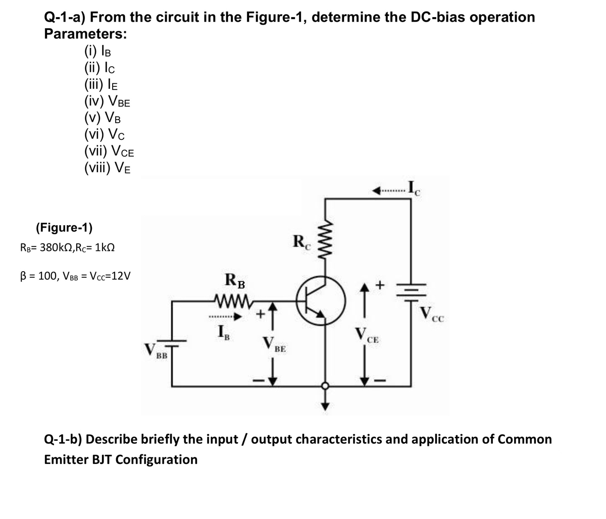
Transcribed Image Text:Q-1-a) From the circuit in the Figure-1, determine the DC-bias operation
Parameters:
(i) IB
(ii) Ic
(iii) le
(iv) VBE
(v) VB
(vi) Vc
(vii) VCE
(viii) Ve
(Figure-1)
Re
RB= 380kN,Rc= 1kN
B = 100, VBB = Vcc=12V
RB
ВЕ
BB
Q-1-b) Describe briefly the input / output characteristics and application of Common
Emitter BJT Configuration
ww
Expert Solution
This question has been solved!
Explore an expertly crafted, step-by-step solution for a thorough understanding of key concepts.

Step by step
Solved in 4 steps with 3 images

Knowledge Booster


Learn more about
Need a deep-dive on the concept behind this application? Look no further. Learn more about this topic, electrical-engineering and related others by exploring similar questions and additional content below.Recommended textbooks for you
Power System Analysis and Design (MindTap Course …
Electrical Engineering
ISBN:
9781305632134
Author:
J. Duncan Glover, Thomas Overbye, Mulukutla S. Sarma
Publisher:
Cengage Learning
Power System Analysis and Design (MindTap Course …
Electrical Engineering
ISBN:
9781305632134
Author:
J. Duncan Glover, Thomas Overbye, Mulukutla S. Sarma
Publisher:
Cengage Learning