After the completion of the activity one you have been asked to run the test to measure the performance of air compressor a lant equipment given in figure 2.1. Your task is to Produce specific Steady Flow Energy Equations based on stated ssumptions in plant equipment given in the table below in table 1. Table 1 At inlet Out let 7bar 5m/s 1.2 bar P C, V, P2 6.3m/s 0.98 m 0.18 m 0.4 kg/s 0.4 kg/s m AU 92 Q 62kW kJ/kg
After the completion of the activity one you have been asked to run the test to measure the performance of air compressor a lant equipment given in figure 2.1. Your task is to Produce specific Steady Flow Energy Equations based on stated ssumptions in plant equipment given in the table below in table 1. Table 1 At inlet Out let 7bar 5m/s 1.2 bar P C, V, P2 6.3m/s 0.98 m 0.18 m 0.4 kg/s 0.4 kg/s m AU 92 Q 62kW kJ/kg

Principles of Heat Transfer (Activate Learning with these NEW titles from Engineering!)
8th Edition
ISBN:9781305387102
Author:Kreith, Frank; Manglik, Raj M.
Publisher:Kreith, Frank; Manglik, Raj M.
Chapter6: Forced Convection Over Exterior Surfaces
Section: Chapter Questions
Problem 6.8P

Related questions

Question
Transcribed Image Text:After the completion of the activity one you have been asked to run the test to measure the performance of air compressor a
plant equipment given in figure 2.1. Your task is to Produce specific Steady Flow Energy Equations based on stated
assumptions in plant equipment given in the table below in table 1.
Table 1
At inlet
Out let
P,
1.2 bar
P2
C,
V;
7bar
6.3m/s
5m/s
V,
0.98 m³
0.18 m³
0.4 kg/s
0.4 kg/s
m
AU
92
Q
62kW
kJ/kg
Air in
Air out
Water in
Air Compressor
Water out
W
Figure 2.1
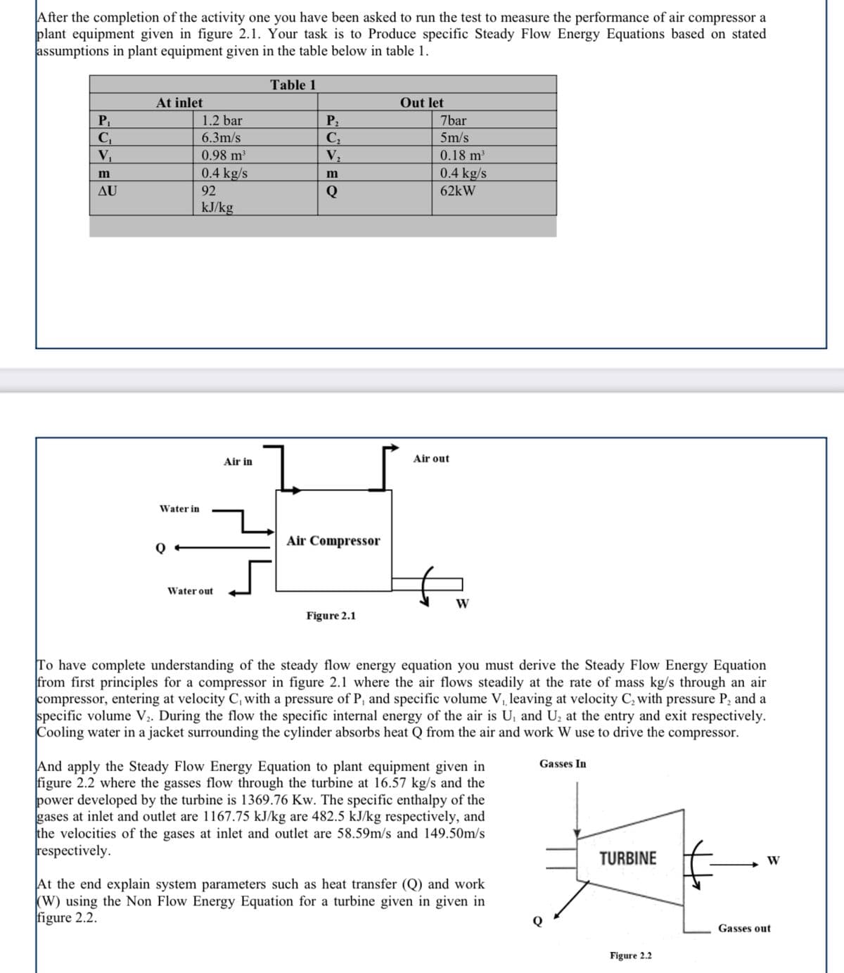
To have complete understanding of the steady flow energy equation you must derive the Steady Flow Energy Equation
from first principles for a compressor in figure 2.1 where the air flows steadily at the rate of mass kg/s through an air
compressor, entering at velocity C, with a pressure of P, and specific volume V, leaving at velocity C, with pressure P, and a
specific volume V2. During the flow the specific internal energy of the air is U, and U, at the entry and exit respectively.
Cooling water in a jacket surrounding the cylinder absorbs heat Q from the air and work W use to drive the compressor.
And apply the Steady Flow Energy Equation to plant equipment given in
figure 2.2 where the gasses flow through the turbine at 16.57 kg/s and the
power developed by the turbine is 1369.76 Kw. The specific enthalpy of the
gases at inlet and outlet are 1167.75 kJ/kg are 482.5 kJ/kg respectively, and
the velocities of the gases at inlet and outlet are 58.59m/s and 149.50m/s
respectively.
Gasses In
TURBINE
W
At the end explain system parameters such as heat transfer (Q) and work
(W) using the Non Flow Energy Equation for a turbine given in given in
figure 2.2.
Gasses out
Figure 2.2
Expert Solution
This question has been solved!
Explore an expertly crafted, step-by-step solution for a thorough understanding of key concepts.

Step by step
Solved in 3 steps

Knowledge Booster


Learn more about
Need a deep-dive on the concept behind this application? Look no further. Learn more about this topic, mechanical-engineering and related others by exploring similar questions and additional content below.Recommended textbooks for you
Principles of Heat Transfer (Activate Learning wi…
Mechanical Engineering
ISBN:
9781305387102
Author:
Kreith, Frank; Manglik, Raj M.
Publisher:
Cengage Learning
Principles of Heat Transfer (Activate Learning wi…
Mechanical Engineering
ISBN:
9781305387102
Author:
Kreith, Frank; Manglik, Raj M.
Publisher:
Cengage Learning