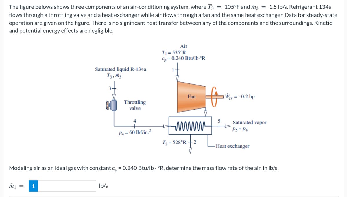
The figure belows shows three components of an air-conditioning system, where T3 = 105°F and m3 = 1.5 lb/s. Refrigerant 134a flows through a throttling valve and a heat exchanger while air flows through a fan and the same heat exchanger. Data for steady-state operation are given on the figure. There is no significant heat transfer between any of the components and the surroundings. Kinetic and potential energy effects are negligible. Air T = 535°R C, = 0.240 Btu/lb-°R Saturated liquid R-134a T3, ṁ3 Fan Wey = -0.2 hp Throttling valve Saturated vapor P5=P4 P4 = 60 lbf/in.2 T= 528°R 2 Heat exchanger Modeling air as an ideal gas with constant c, = 0.240 Btu/lb · °R, determine the mass flow rate of the air, in lb/s. m¡ = i Ib/s
The figure belows shows three components of an air-conditioning system, where T3 = 105°F and m3 = 1.5 lb/s. Refrigerant 134a flows through a throttling valve and a heat exchanger while air flows through a fan and the same heat exchanger. Data for steady-state operation are given on the figure. There is no significant heat transfer between any of the components and the surroundings. Kinetic and potential energy effects are negligible. Air T = 535°R C, = 0.240 Btu/lb-°R Saturated liquid R-134a T3, ṁ3 Fan Wey = -0.2 hp Throttling valve Saturated vapor P5=P4 P4 = 60 lbf/in.2 T= 528°R 2 Heat exchanger Modeling air as an ideal gas with constant c, = 0.240 Btu/lb · °R, determine the mass flow rate of the air, in lb/s. m¡ = i Ib/s

Elements Of Electromagnetics
7th Edition
ISBN:9780190698614
Author:Sadiku, Matthew N. O.
Publisher:Sadiku, Matthew N. O.
ChapterMA: Math Assessment
Section: Chapter Questions
Problem 1.1MA

Related questions
Question
Transcribed Image Text:The figure belows shows three components of an air-conditioning system, where T3 = 105°F and m3 = 1.5 lb/s. Refrigerant 134a
flows through a throttling valve and a heat exchanger while air flows through a fan and the same heat exchanger. Data for steady-state
operation are given on the figure. There is no significant heat transfer between any of the components and the surroundings. Kinetic
and potential energy effects are negligible.
Air
T1 = 535°R
C, = 0.240 Btu/lb-°R
Saturated liquid R-134a
T3, ṁ3
3.
Fan
= -0.2 hp
Throttling
valve
Saturated vapor
P5=P4
P4 = 60 lbf/in.2
T2= 528°R
2
Heat exchanger
Modeling air as an ideal gas with constant c, = 0.240 Btu/lb · °R, determine the mass flow rate of the air, in Ib/s.
m¡ =
i
Ib/s
Expert Solution
This question has been solved!
Explore an expertly crafted, step-by-step solution for a thorough understanding of key concepts.

This is a popular solution!

Trending now
This is a popular solution!

Step by step
Solved in 2 steps with 2 images

Recommended textbooks for you
Elements Of Electromagnetics
Mechanical Engineering
ISBN:
9780190698614
Author:
Sadiku, Matthew N. O.
Publisher:
Oxford University Press

Mechanics of Materials (10th Edition)
Mechanical Engineering
ISBN:
9780134319650
Author:
Russell C. Hibbeler
Publisher:
PEARSON

Thermodynamics: An Engineering Approach
Mechanical Engineering
ISBN:
9781259822674
Author:
Yunus A. Cengel Dr., Michael A. Boles
Publisher:
McGraw-Hill Education
Elements Of Electromagnetics
Mechanical Engineering
ISBN:
9780190698614
Author:
Sadiku, Matthew N. O.
Publisher:
Oxford University Press
Mechanics of Materials (10th Edition)
Mechanical Engineering
ISBN:
9780134319650
Author:
Russell C. Hibbeler
Publisher:
PEARSON
Thermodynamics: An Engineering Approach
Mechanical Engineering
ISBN:
9781259822674
Author:
Yunus A. Cengel Dr., Michael A. Boles
Publisher:
McGraw-Hill Education

Control Systems Engineering
Mechanical Engineering
ISBN:
9781118170519
Author:
Norman S. Nise
Publisher:
WILEY

Mechanics of Materials (MindTap Course List)
Mechanical Engineering
ISBN:
9781337093347
Author:
Barry J. Goodno, James M. Gere
Publisher:
Cengage Learning

Engineering Mechanics: Statics
Mechanical Engineering
ISBN:
9781118807330
Author:
James L. Meriam, L. G. Kraige, J. N. Bolton
Publisher:
WILEY