An electrical fan is used to cool electrical components when the temperature exceeds a certain limit. The fan is trolled by a microcontroller that sends a logical-1 (3.3V) to an interface circuit that in tum activates the motor. When temperature falls below the upper limit, the microcontroller sends a logical-0 (0.0V) to the interface circuit and the or turns off. are to design a simple transistor switch controller circuit for this application and decide to use the design shown Fan motor draws 24W when running "GND -24V D2 IN4001OP "DO NPN Transistor ow. You have the following npn transistors available to you: 2N2222A, SS8050, and 2N3904. If the fan draws 24W when running, what is the collector current, Ic? What would the maximum Vce voltage be across the transistor when the it is in cut-off? Based on the design criteria and the manufacturer's specifications for the 3 transistors, which one would work for this application? Why?
An electrical fan is used to cool electrical components when the temperature exceeds a certain limit. The fan is trolled by a microcontroller that sends a logical-1 (3.3V) to an interface circuit that in tum activates the motor. When temperature falls below the upper limit, the microcontroller sends a logical-0 (0.0V) to the interface circuit and the or turns off. are to design a simple transistor switch controller circuit for this application and decide to use the design shown Fan motor draws 24W when running "GND -24V D2 IN4001OP "DO NPN Transistor ow. You have the following npn transistors available to you: 2N2222A, SS8050, and 2N3904. If the fan draws 24W when running, what is the collector current, Ic? What would the maximum Vce voltage be across the transistor when the it is in cut-off? Based on the design criteria and the manufacturer's specifications for the 3 transistors, which one would work for this application? Why?

Introductory Circuit Analysis (13th Edition)
13th Edition
ISBN:9780133923605
Author:Robert L. Boylestad
Publisher:Robert L. Boylestad
Chapter1: Introduction
Section: Chapter Questions
Problem 1P: Visit your local library (at school or home) and describe the extent to which it provides literature...

Related questions

Question
100%
Transcribed Image Text:3.
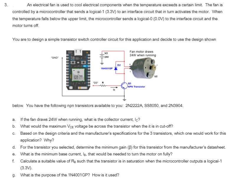
An electrical fan is used to cool electrical components when the temperature exceeds a certain limit. The fan is
controlled by a microcontroller that sends a logical-1 (3.3V) to an interface circuit that in turn activates the motor. When
the temperature falls below the upper limit, the microcontroller sends a logical-0 (0.0V) to the interface circuit and the
motor turns off.
You are to design a simple transistor switch controller circuit for this application and decide to use the design shown
Fan motor draws
V2
24W when running
"GND
-24V
D2
IN40010P
u2
"DO"
as
NPN Transistor
Ib
below. You have the following npn transistors available to you: 2N2222A, SS8050, and 2N3904.
a. If the fan draws 24W when running, what is the collector current, Ic?
b. What would the maximum Vce voltage be across the transistor when the it is in cut-off?
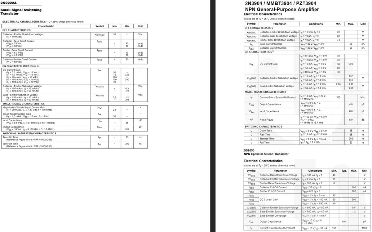
c. Based on the design criteria and the manufacturer's specifications for the 3 transistors, which one would work for this
application? Why?
d. For the transistor you selected, determine the minimum gain (B) for this transistor from the manufacturer's datasheet.
e. What is the minimum base current, Is, that would be needed to turn the motor on fully?
f. Calculate a suitable value of Rg such that the transistor is in saturation when the microcontroller outputs a logical-1
(3.3V).
g. What is the purpose of the 1N4001GP? How is it used?
Transcribed Image Text:2N2222A
2N3904 / MMBT3904 / PZT3904
NPN General-Purpose Amplifier
Small Signal Switching
Transistor
Electrical Characteristics
Values are at TA = 25°C unless otherwise noted.
ELECTRICAL CHARACTERISTICS (TA= 25°C unless otherwise noted)
Symbol
Parameter
Conditions
Min.
Мах.
Unit
Characteristic
Symbol
Min
Max
Unit
OFF CHARACTERISTICS
OFF CHARACTERISTICS
VBRCEO Collector-Emitter Breakdown Voltage Ic = 1.0 mA, Ig = 0
VBRICBO Collector-Base Breakdown Voltage Ic 10 pA, lE 0
le = 10 µA, le = 0
VCE 30 V, VEB = 3 V
Vce " 30 V, Ves= 3 W
40
V
Colector-Emitter Breakdown Voltage
(le 10 mAdc)
VBRICEO
50
Vdc
60
V
Emitter-Base Breakdown Voltage
Base Cut-Off Current
Collector Cut-Off Current
VBREBO
6.0
V
Collector-Base Cutoff Current
(Vce= 75 Vdc)
(Ven = 60 Vdc)
Iceo
10
HAdc
nAdc
IBL
50
nA
50
ICEX
ON CHARACTERISTICS5)
nA
Emitter-Base Cutoff Current
(VEe = 60 Vdc
(Ven =4.0 Vdc)
10
10
HAdc
nAdc
c = 0.1 mA VcE 1.0 V
lc= 1.0 mA, VcE 1.0 V
c= 10 mA, VCE 1.0 V
Ic = 50 mA, VcE = 1.0 V
Iç =100 mA, VCE= 1.0V
40
Collector-Emitter Cutoff Current
ICES
50
nAdc
70
(Vce = 50 vdc)
hFE
DC Current Gain
100
300
ON CHARACTERISTICS (Note 1)
DC Current Gain
(le = 0.1 mAdc, Ver = 10 Vdc)
de 10 mAdc. Ver= 10 Vdc
(Iç = 10 mAdc, VCE = 10 Vdc)
le = 150 mAdc, Vce = 10 Vdc)
(le = 500 mAdc, VcE = 10 Vdc)
60
hFE
30
50
75
100
100
30
325
Ic 10 mA, 1.0 mA
02
VcE(sat) Collector-Emitter Saturation Voltage
V
lc=50 mA, lg=5.0 mA
lc = 10 mA, Ig = 1.0 mA
Ic 50 mA, In5.0 mA
300
0.3
0.65
0.85
Collector-Emitter Saturation Voltage
(le = 150 mAdc, la = 15 mAdc)
lc = 500 mAdc, lg = 50 mAdc)
VCEsat)
Vdc
Veglsat) Base-Emitter Saturation Voltage
V
0.95
0.3
1.0
SMALL SIGNAL CHARACTERISTICS
Base-Emitter Saturation Voltage
(lc = 150 mAdc, la= 15 mAdc)
(Iç = 500 mAdc, lg = 50 mAdc)
Vdc
lc = 10 mA, VcE = 20 V
f= 100 MHz
VcB = 5.0 V, le" 0,
f= 100 kHz
VER = 0.5 V, le = 0,
f= 100 kHz
lc = 100 HA. VeE =5.0 V.
Rs = 1.0 ks2
f= 10 Hz to 15.7 kHz
0.6
1.2
20
Current Gain - Bandwidth Product
fT
300
MHz
SMALL- SIGNAL CHARACTERISTICS
Magnitude of Smal-Signal Current Gain
(lc= 20 mAdc, Vce 20 Vdc, f= 100 MHz)
Small-Signal Current Gain
(lc = 1.0 mAdc, VCE = 10 Vdc, f= 1 KHZ)
Cobo
Output Capacitance
4.0
pF
2.5
Cbo
Input Capacitance
8.0
pF
he
50
NF
Noise Figure
5.0
dB
Input Capacitance
(VEB = 0.5 Vdc, lç = 0, 100 KHz Sts 1.0 MHz)
Outout Capacitance
(Vce = 10 Vdc, lg =0,100 KHZ s fs 1.0 MHZ)
Coo
pF
25
SWITCHING CHARACTERISTICS
Delay Time
Rise Time
Storage Time
Fall Time
Cobo
pF
8.0
Vcc = 3.0 V. VBe-0.5 V
Iç = 10 mA, l81 =1.0 mA
35
ns
SWITCHING (SATURATED) CHARACTERISTICS
35
ns
Turn-On Time
(Reference Figure in MIL-PRF-19500/255)
on
35
ns
Vcc = 3.0 V. lc 10 mA.
B1= le2 1.0 mA
200
ns
50
ns
Turn-Off Time
(Reference Figure in MIL-PRF-19500/255)
300
ns
SS8050
NPN Epitaxial Silicon Transistor
Electrical Characteristics
Values are at TA = 25°C unless otherwise noted.
Symbol
Conditions
Parameter
Min.
Тур.
Мах.
Unit
c= 100 HA, lg= 0
Collector-Emitter Breakdown Voltagec=2 mA, Ig= 0
= 100 µA, Ic = 0
Collector-Base Breakdown Voltage
BVCBO
BVCEO
40
V
25
V
BVEBO
Emitter-Base Breakdown Voltage
6
V
Icao
Collector Cut-Of Current
Vca = 35 V, lg = 0
100
nA
Ves = 6 V. le =0
VCE= 1 V, lç = 5 mA
VCE1 V, lc= 100 mA
VCE = 1 V, le = 800 mA
lc = 800 mA, Ig = 80 mA
Emitter Cut-Off Current
100
nA
45
DC Current Gain
85
300
40
VcE(sat)
Collector-Emiter Saturation Voltage
0.5
V
VeE(sat) Base-Emitter Saturation Voltage
c= 800 mA, Ig = 80 mA
1.2
V
Veelon)
Base-Emitter On Voltage
Vce1 V, le= 10 mA
1.
Cob
Output Capacitance
Vce = 10 V, le = 0,
9.0
pF
f= 1 MHz
Current Gain Bandwidth Product
VcE = 10 V, le= 50 mA
100
MHz
Expert Solution
This question has been solved!
Explore an expertly crafted, step-by-step solution for a thorough understanding of key concepts.

This is a popular solution!

Trending now
This is a popular solution!

Step by step
Solved in 2 steps with 1 images

Knowledge Booster


Learn more about
Need a deep-dive on the concept behind this application? Look no further. Learn more about this topic, electrical-engineering and related others by exploring similar questions and additional content below.Recommended textbooks for you
Introductory Circuit Analysis (13th Edition)
Electrical Engineering
ISBN:
9780133923605
Author:
Robert L. Boylestad
Publisher:
PEARSON

Delmar's Standard Textbook Of Electricity
Electrical Engineering
ISBN:
9781337900348
Author:
Stephen L. Herman
Publisher:
Cengage Learning

Programmable Logic Controllers
Electrical Engineering
ISBN:
9780073373843
Author:
Frank D. Petruzella
Publisher:
McGraw-Hill Education
Introductory Circuit Analysis (13th Edition)
Electrical Engineering
ISBN:
9780133923605
Author:
Robert L. Boylestad
Publisher:
PEARSON
Delmar's Standard Textbook Of Electricity
Electrical Engineering
ISBN:
9781337900348
Author:
Stephen L. Herman
Publisher:
Cengage Learning
Programmable Logic Controllers
Electrical Engineering
ISBN:
9780073373843
Author:
Frank D. Petruzella
Publisher:
McGraw-Hill Education

Fundamentals of Electric Circuits
Electrical Engineering
ISBN:
9780078028229
Author:
Charles K Alexander, Matthew Sadiku
Publisher:
McGraw-Hill Education

Electric Circuits. (11th Edition)
Electrical Engineering
ISBN:
9780134746968
Author:
James W. Nilsson, Susan Riedel
Publisher:
PEARSON

Engineering Electromagnetics
Electrical Engineering
ISBN:
9780078028151
Author:
Hayt, William H. (william Hart), Jr, BUCK, John A.
Publisher:
Mcgraw-hill Education,