1. The op-amp in the circuit is ideal, except for non-zero input bias currents. Further, R1 =10K and R2 = 30K. What should R3's value be? R R2 (а) 10K (b) R1 + R2 = 30K (c) 0 N (d) R1||R2 = 7.5K
1. The op-amp in the circuit is ideal, except for non-zero input bias currents. Further, R1 =10K and R2 = 30K. What should R3's value be? R R2 (а) 10K (b) R1 + R2 = 30K (c) 0 N (d) R1||R2 = 7.5K

Introductory Circuit Analysis (13th Edition)
13th Edition
ISBN:9780133923605
Author:Robert L. Boylestad
Publisher:Robert L. Boylestad
Chapter1: Introduction
Section: Chapter Questions
Problem 1P: Visit your local library (at school or home) and describe the extent to which it provides literature...

Related questions
Question
1. The op-amp in the circuit is ideal, except for non-zero input bias currents. Further, ?1 =10K and ?2 = 30K. What should ?3′? value be?
(a) 10K
(b)?1 +?2 =30K (c) 0 Ω
(d) ?1||?2 = 7.5K
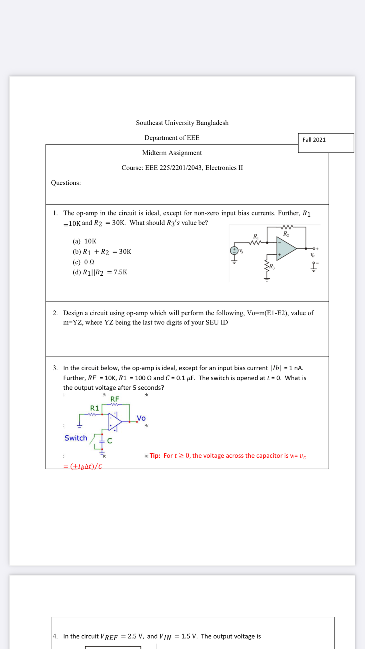
Transcribed Image Text:Southeast University Bangladesh
Department of EEE
Fall 2021
Midterm Assignment
Course: EEE 225/2201/2043, Electronics II
Questions:
1. The op-amp in the circuit is ideal, except for non-zero input bias currents. Further, R1
-10K and R2 = 30K. What should R3's value be?
R2
(а) 10K
(b) R1 + R2 = 30K
(с) 0
(d) R1||R2 = 7.5K
2. Design a circuit using op-amp which will perform the following, Vo=m(E1-E2), value of
m=YZ, where YZ being the last two digits of your SEU ID
3. In the circuit below, the op-amp is ideal, except for an input bias current |Ib| = 1 nA.
urther, RF = 1OK, R1 = 100 Q and C = 0.1 µF. The switch is opened at t = 0. What is
the output voltage after 5 seconds?
RF
R1
Vo
Switch
* Tip: For t> 0, the voltage across the capacitor is v;= vc
= (+IþAt)/C_
|4. In the circuit VREF = 2.5 V, and VIN
= 1.5 V. The output voltage is
Expert Solution
This question has been solved!
Explore an expertly crafted, step-by-step solution for a thorough understanding of key concepts.

Step by step
Solved in 2 steps with 1 images

Knowledge Booster


Learn more about
Need a deep-dive on the concept behind this application? Look no further. Learn more about this topic, electrical-engineering and related others by exploring similar questions and additional content below.Recommended textbooks for you
Introductory Circuit Analysis (13th Edition)
Electrical Engineering
ISBN:
9780133923605
Author:
Robert L. Boylestad
Publisher:
PEARSON

Delmar's Standard Textbook Of Electricity
Electrical Engineering
ISBN:
9781337900348
Author:
Stephen L. Herman
Publisher:
Cengage Learning

Programmable Logic Controllers
Electrical Engineering
ISBN:
9780073373843
Author:
Frank D. Petruzella
Publisher:
McGraw-Hill Education
Introductory Circuit Analysis (13th Edition)
Electrical Engineering
ISBN:
9780133923605
Author:
Robert L. Boylestad
Publisher:
PEARSON
Delmar's Standard Textbook Of Electricity
Electrical Engineering
ISBN:
9781337900348
Author:
Stephen L. Herman
Publisher:
Cengage Learning
Programmable Logic Controllers
Electrical Engineering
ISBN:
9780073373843
Author:
Frank D. Petruzella
Publisher:
McGraw-Hill Education

Fundamentals of Electric Circuits
Electrical Engineering
ISBN:
9780078028229
Author:
Charles K Alexander, Matthew Sadiku
Publisher:
McGraw-Hill Education

Electric Circuits. (11th Edition)
Electrical Engineering
ISBN:
9780134746968
Author:
James W. Nilsson, Susan Riedel
Publisher:
PEARSON

Engineering Electromagnetics
Electrical Engineering
ISBN:
9780078028151
Author:
Hayt, William H. (william Hart), Jr, BUCK, John A.
Publisher:
Mcgraw-hill Education,