An RLC circuit consists of a 150 Ohm resistor, a 12.5 uF capacitor and a 6 mH inductor, connected in series to an AC source with a maximum voltage (∆Vmax) of 120 V. Calculate: a. The frequency on which the impedance on the circuit has its minimum value. b. For the value of the frequency calculated on a. calculate the maximum current through the inductor. c. For the frequency calculated on a. calculate the potential difference of the AC source, the resistor, the inductor and the capacitor on a time instance on which the magnitud of the current on the circuit is half of its maximum positive value. Calculate c.
An RLC circuit consists of a 150 Ohm resistor, a 12.5 uF capacitor and a 6 mH inductor, connected in series to an AC source with a maximum voltage (∆Vmax) of 120 V. Calculate: a. The frequency on which the impedance on the circuit has its minimum value. b. For the value of the frequency calculated on a. calculate the maximum current through the inductor. c. For the frequency calculated on a. calculate the potential difference of the AC source, the resistor, the inductor and the capacitor on a time instance on which the magnitud of the current on the circuit is half of its maximum positive value. Calculate c.

Delmar's Standard Textbook Of Electricity
7th Edition
ISBN:9781337900348
Author:Stephen L. Herman
Publisher:Stephen L. Herman
Chapter20: Capacitance In Ac Circuits
Section: Chapter Questions
Problem 12RQ: What is the minimum AC voltage rating of each capacitor in Question 11?

Related questions
Question
An RLC circuit consists of a 150 Ohm resistor, a 12.5 uF capacitor and a 6 mH inductor, connected in series to an AC source with a maximum voltage (∆Vmax) of 120 V. Calculate:
a. The frequency on which the impedance on the circuit has its minimum value.
b. For the value of the frequency calculated on a. calculate the maximum current through the inductor.
c. For the frequency calculated on a. calculate the potential difference of the AC source, the resistor, the inductor and the capacitor on a time instance on which the magnitud of the current on the circuit is half of its maximum positive value.
Calculate c.
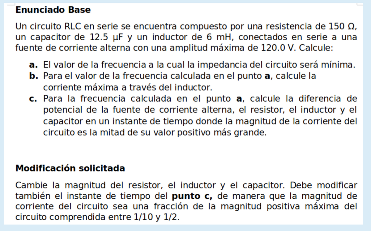
Transcribed Image Text:Enunciado Base
Un circuito RLC en serie se encuentra compuesto por una resistencia de 150 Q,
un capacitor de 12.5 µF y un inductor de 6 mH, conectados en serie a una
fuente de corriente alterna con una amplitud máxima de 120.0 V. Calcule:
a. El valor de la frecuencia a la cual la impedancia del circuito será mínima.
b. Para el valor de la frecuencia calculada en el punto a, calcule la
corriente máxima a través del inductor.
c. Para la frecuencia calculada en el punto a, calcule la diferencia de
potencial de la fuente de corriente alterna, el resistor, el inductor y el
capacitor en un instante de tiempo donde la magnitud de la corriente del
circuito es la mitad de su valor positivo más grande.
Modificación solicitada
Cambie la magnitud del resistor, el inductor y el capacitor. Debe modificar
también el instante de tiempo del punto c, de manera que la magnitud de
corriente del circuito sea una fracción de la magnitud positiva máxima del
circuito comprendida entre 1/10 y 1/2.
Expert Solution
This question has been solved!
Explore an expertly crafted, step-by-step solution for a thorough understanding of key concepts.

This is a popular solution!

Trending now
This is a popular solution!

Step by step
Solved in 4 steps with 4 images

Knowledge Booster


Learn more about
Need a deep-dive on the concept behind this application? Look no further. Learn more about this topic, electrical-engineering and related others by exploring similar questions and additional content below.Recommended textbooks for you
Delmar's Standard Textbook Of Electricity
Electrical Engineering
ISBN:
9781337900348
Author:
Stephen L. Herman
Publisher:
Cengage Learning
Delmar's Standard Textbook Of Electricity
Electrical Engineering
ISBN:
9781337900348
Author:
Stephen L. Herman
Publisher:
Cengage Learning