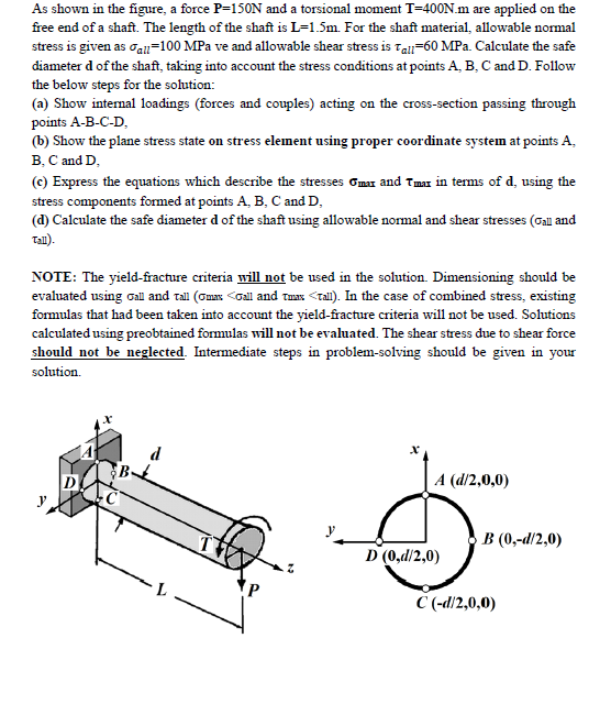
As shown in the figure, a force P-150N and a torsional moment T=400N.m are applied on the free end of a shaft. The length of the shaft is L-1.5m. For the shaft material, allowable normal stress is given as oall-100 MPa ve and allowable shear stress is Tal-60 MPa. Calculate the safe diameter d of the shaft, taking into account the stress conditions at points A, B, C and D. Follow the below steps for the solution: (a) Show internal loadings (forces and couples) acting on the cross-section passing through points A-B-C-D, (b) Show the plane stress state on stress element using proper coordinate system at points A, B, C and D, (c) Express the equations which describe the stresses Gmax and Tmax in terms of d, using the stress components formed at points A, B, C and D, (d) Calculate the safe diameter d of the shaft using allowable normal and shear stresses (Oall and Tall).
As shown in the figure, a force P-150N and a torsional moment T=400N.m are applied on the free end of a shaft. The length of the shaft is L-1.5m. For the shaft material, allowable normal stress is given as oall-100 MPa ve and allowable shear stress is Tal-60 MPa. Calculate the safe diameter d of the shaft, taking into account the stress conditions at points A, B, C and D. Follow the below steps for the solution: (a) Show internal loadings (forces and couples) acting on the cross-section passing through points A-B-C-D, (b) Show the plane stress state on stress element using proper coordinate system at points A, B, C and D, (c) Express the equations which describe the stresses Gmax and Tmax in terms of d, using the stress components formed at points A, B, C and D, (d) Calculate the safe diameter d of the shaft using allowable normal and shear stresses (Oall and Tall).

Mechanics of Materials (MindTap Course List)
9th Edition
ISBN:9781337093347
Author:Barry J. Goodno, James M. Gere
Publisher:Barry J. Goodno, James M. Gere
Chapter3: Torsion
Section: Chapter Questions
Problem 3.8.14P: The composite shaft shown in the figure is manufactured by shrink-Fitting a steel sleeve over a...

Related questions

Question
Transcribed Image Text:As shown in the figure, a force P-150N and a torsional moment T=400N.m are applied on the
free end of a shaft. The length of the shaft is L-1.5m. For the shaft material, allowable normal
stress is given as oall-100 MPa ve and allowable shear stress is Tal-60 MPa. Calculate the safe
diameter d of the shaft, taking into account the stress conditions at points A, B, C and D. Follow
the below steps for the solution:
(a) Show internal loadings (forces and couples) acting on the cross-section passing through
points A-B-C-D,
(b) Show the plane stress state on stress element using proper coordinate system at points A,
B, C and D,
(c) Express the equations which describe the stresses Gmax and Tmax in terms of d, using the
stress components formed at points A, B, C and D,
(d) Calculate the safe diameter d of the shaft using allowable normal and shear stresses (Oall and
Tall).
Expert Solution
This question has been solved!
Explore an expertly crafted, step-by-step solution for a thorough understanding of key concepts.

Step by step
Solved in 7 steps with 15 images

Knowledge Booster


Learn more about
Need a deep-dive on the concept behind this application? Look no further. Learn more about this topic, mechanical-engineering and related others by exploring similar questions and additional content below.Recommended textbooks for you
Mechanics of Materials (MindTap Course List)
Mechanical Engineering
ISBN:
9781337093347
Author:
Barry J. Goodno, James M. Gere
Publisher:
Cengage Learning
Mechanics of Materials (MindTap Course List)
Mechanical Engineering
ISBN:
9781337093347
Author:
Barry J. Goodno, James M. Gere
Publisher:
Cengage Learning