(Assume the clocks of flip-flops are connected.) (FA block is full adder.) Q2 Q0-10 Q2- Q1–11 Q2 S3 2x4 QO 10 D Q1 Q1 Q1-11 Q1 Q2-A FA S Q1-в Сout QO- QO 0 Cin QO 6123 SSSS
(Assume the clocks of flip-flops are connected.) (FA block is full adder.) Q2 Q0-10 Q2- Q1–11 Q2 S3 2x4 QO 10 D Q1 Q1 Q1-11 Q1 Q2-A FA S Q1-в Сout QO- QO 0 Cin QO 6123 SSSS

Chapter22: Sequence Control
Section: Chapter Questions
Problem 6SQ: Draw a symbol for a solid-state logic element AND.

Related questions
Question
erfsdfdsdsffds
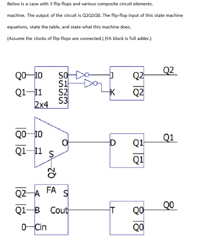
Transcribed Image Text:Below is a case with 3 flip-flops and various composite circuit elements.
machine. The output of the circuit is Q2Q100. The flip-flop input of this state machine
equations, state the table, and state what this machine does.
(Assume the clocks of flip-flops are connected.) (FA block is full adder.)
Q2
Q2-
Q0-10
S1
S2
SO
Q1–11
S3
Q2
2x4
Q0 10
Q1
Q1
Q1-11 s
Q1
FA
Q2-A
QO
Q1-В Сout
QO-
0-Cin
QO
Expert Solution
This question has been solved!
Explore an expertly crafted, step-by-step solution for a thorough understanding of key concepts.

Step by step
Solved in 4 steps with 3 images

Knowledge Booster


Learn more about
Need a deep-dive on the concept behind this application? Look no further. Learn more about this topic, electrical-engineering and related others by exploring similar questions and additional content below.Recommended textbooks for you