b) Calculate support reactions in A and C, remember the sign of the force. Reaction force at point A: x-direction: XA= N, y-direction: YA= Reaction force at point C: x-direction: Xc= N, y-direction: Yc=
b) Calculate support reactions in A and C, remember the sign of the force. Reaction force at point A: x-direction: XA= N, y-direction: YA= Reaction force at point C: x-direction: Xc= N, y-direction: Yc=

Mechanics of Materials (MindTap Course List)
9th Edition
ISBN:9781337093347
Author:Barry J. Goodno, James M. Gere
Publisher:Barry J. Goodno, James M. Gere
Chapter1: Tension, Compression, And Shear
Section: Chapter Questions
Problem 1.9.10P: A cable and pulley system in the figure part a supports a cage of a mass 300 kg at B. Assume that...

Related questions
Question
Transcribed Image Text:Qb
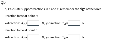
b) Calculate support reactions in A and C, remember the sign of the force.
Reaction force at point A:
x-direction: XA=
N, y-direction: YA=
Reaction force at point C:
x-direction: Xc=
N, y-direction: Yc=
N
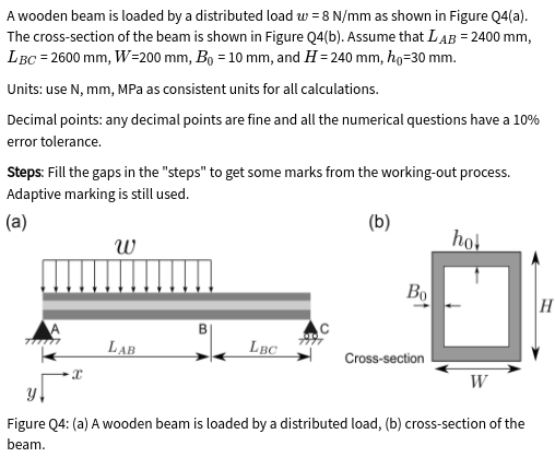
Transcribed Image Text:A wooden beam is loaded by a distributed load w = 8 N/mm as shown in Figure Q4(a).
The cross-section of the beam is shown in Figure Q4(b). Assume that LAB = 2400 mm,
LBC = 2600 mm, W=200 mm, Bo = 10 mm, and H= 240 mm, ho=30 mm.
Units: use N, mm, MPa as consistent units for all calculations.
Decimal points: any decimal points are fine and all the numerical questions have a 10%
error tolerance.
Steps: Fill the gaps in the "steps" to get some marks from the working-out process.
Adaptive marking is still used.
(а)
(b)
w
hot
Bo
H
LAB
LBC
Cross-section
W
Figure Q4: (a) A wooden beam is loaded by a distributed load, (b) cross-section of the
beam.
Expert Solution
This question has been solved!
Explore an expertly crafted, step-by-step solution for a thorough understanding of key concepts.

This is a popular solution!

Trending now
This is a popular solution!

Step by step
Solved in 2 steps with 2 images

Knowledge Booster


Learn more about
Need a deep-dive on the concept behind this application? Look no further. Learn more about this topic, mechanical-engineering and related others by exploring similar questions and additional content below.Recommended textbooks for you
Mechanics of Materials (MindTap Course List)
Mechanical Engineering
ISBN:
9781337093347
Author:
Barry J. Goodno, James M. Gere
Publisher:
Cengage Learning
Mechanics of Materials (MindTap Course List)
Mechanical Engineering
ISBN:
9781337093347
Author:
Barry J. Goodno, James M. Gere
Publisher:
Cengage Learning