(b) Calculate the line voltage (in kV) at bus B and the complex power at the sending end of the transmission line.
(b) Calculate the line voltage (in kV) at bus B and the complex power at the sending end of the transmission line.

Power System Analysis and Design (MindTap Course List)
6th Edition
ISBN:9781305632134
Author:J. Duncan Glover, Thomas Overbye, Mulukutla S. Sarma
Publisher:J. Duncan Glover, Thomas Overbye, Mulukutla S. Sarma
Chapter3: Power Transformers
Section: Chapter Questions
Problem 3.24MCQ: It is stated that (i) balanced three-phase circuits can be solved in per unit on a per-phase basis...

Related questions

Question
Solve B only neatly
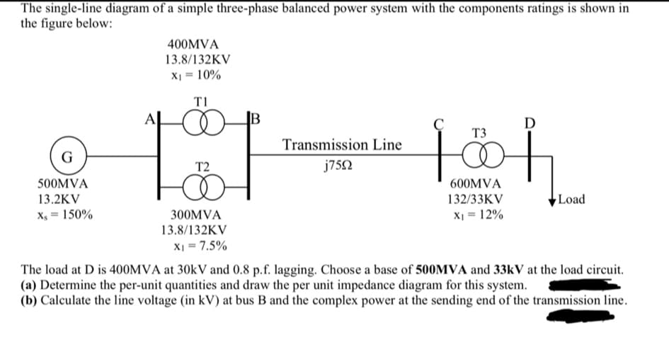
Transcribed Image Text:The single-line diagram of a simple three-phase balanced power system with the components ratings is shown in
the figure below:
G
500MVA
13.2KV
Xs = 150%
400MVA
13.8/132KV
X₁ = 10%
T1
T2
300MVA
13.8/132KV
X1 = 7.5%
Transmission Line
j75Ω
с
T3
600MVA
132/33KV
X₁ = 12%
D
f
Load
The load at D is 400MVA at 30kV and 0.8 p.f. lagging. Choose a base of 500MVA and 33kV at the load circuit.
(a) Determine the per-unit quantities and draw the per unit impedance diagram for this system.
(b) Calculate the line voltage (in kV) at bus B and the complex power at the sending end of the transmission line.
Expert Solution
This question has been solved!
Explore an expertly crafted, step-by-step solution for a thorough understanding of key concepts.

Step by step
Solved in 3 steps with 3 images

Knowledge Booster


Learn more about
Need a deep-dive on the concept behind this application? Look no further. Learn more about this topic, electrical-engineering and related others by exploring similar questions and additional content below.Recommended textbooks for you
Power System Analysis and Design (MindTap Course …
Electrical Engineering
ISBN:
9781305632134
Author:
J. Duncan Glover, Thomas Overbye, Mulukutla S. Sarma
Publisher:
Cengage Learning
Power System Analysis and Design (MindTap Course …
Electrical Engineering
ISBN:
9781305632134
Author:
J. Duncan Glover, Thomas Overbye, Mulukutla S. Sarma
Publisher:
Cengage Learning