b) Draw a circuit showing how to use a 74LS138 decoder and a 74LS10 NAND gate to implement the equation F = E(2,5,7). The 74LS138 is an "active-low" decoder and the 74LS10 is a positive logic NAND – remember how to use bubble-matching with NAND gates. In the decoder, Pin G1 is connected to Vcc and the G2 pins are not used (connected to GND). The image on the TI.com datasheet is not very clear, here is a better picture of the decoder: 16
b) Draw a circuit showing how to use a 74LS138 decoder and a 74LS10 NAND gate to implement the equation F = E(2,5,7). The 74LS138 is an "active-low" decoder and the 74LS10 is a positive logic NAND – remember how to use bubble-matching with NAND gates. In the decoder, Pin G1 is connected to Vcc and the G2 pins are not used (connected to GND). The image on the TI.com datasheet is not very clear, here is a better picture of the decoder: 16

Introductory Circuit Analysis (13th Edition)
13th Edition
ISBN:9780133923605
Author:Robert L. Boylestad
Publisher:Robert L. Boylestad
Chapter1: Introduction
Section: Chapter Questions
Problem 1P: Visit your local library (at school or home) and describe the extent to which it provides literature...

Related questions

Question
100%
This is a practice problem I am having a little difficulty with understanding.
Thank you for the help.
Transcribed Image Text:O Propagation Delay in Digit X
O Priority Encoder - YouTube x A Full Adder | Neso Academ X
O What is a Clock? - YouTub x
ECE 171 HW 4 - ECE-171- X
+
A https://d2l.pdx.edu/d2l/le/content/876966/viewContent/5892520/View
Update :
6.
G
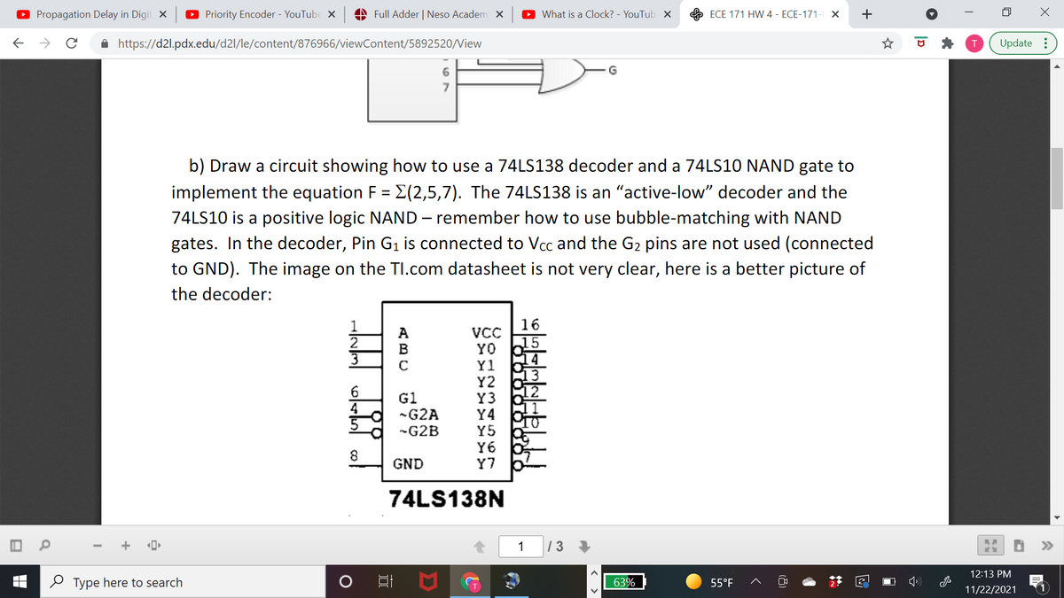
b) Draw a circuit showing how to use a 74LS138 decoder and a 74LS10 NAND gate to
implement the equation F = E(2,5,7). The 74LS138 is an "active-low" decoder and the
74LS10 is a positive logic NAND – remember how to use bubble-matching with NAND
gates. In the decoder, Pin G1 is connected to Vcc and the G2 pins are not used (connected
to GND). The image on the TI.com datasheet is not very clear, here is a better picture of
the decoder:
16
VCC
YO
Y1
Y2
Y3
Y4
Y5
Y6
Y7
2
G1
-G2A
4
-G2B
8.
GND
74LS138N
1
|13
12:13 PM
O Type here to search
63%
55°F
11/22/2021
|D
Expert Solution
This question has been solved!
Explore an expertly crafted, step-by-step solution for a thorough understanding of key concepts.

Step by step
Solved in 5 steps with 2 images

Knowledge Booster


Learn more about
Need a deep-dive on the concept behind this application? Look no further. Learn more about this topic, electrical-engineering and related others by exploring similar questions and additional content below.Recommended textbooks for you
Introductory Circuit Analysis (13th Edition)
Electrical Engineering
ISBN:
9780133923605
Author:
Robert L. Boylestad
Publisher:
PEARSON

Delmar's Standard Textbook Of Electricity
Electrical Engineering
ISBN:
9781337900348
Author:
Stephen L. Herman
Publisher:
Cengage Learning

Programmable Logic Controllers
Electrical Engineering
ISBN:
9780073373843
Author:
Frank D. Petruzella
Publisher:
McGraw-Hill Education
Introductory Circuit Analysis (13th Edition)
Electrical Engineering
ISBN:
9780133923605
Author:
Robert L. Boylestad
Publisher:
PEARSON
Delmar's Standard Textbook Of Electricity
Electrical Engineering
ISBN:
9781337900348
Author:
Stephen L. Herman
Publisher:
Cengage Learning
Programmable Logic Controllers
Electrical Engineering
ISBN:
9780073373843
Author:
Frank D. Petruzella
Publisher:
McGraw-Hill Education

Fundamentals of Electric Circuits
Electrical Engineering
ISBN:
9780078028229
Author:
Charles K Alexander, Matthew Sadiku
Publisher:
McGraw-Hill Education

Electric Circuits. (11th Edition)
Electrical Engineering
ISBN:
9780134746968
Author:
James W. Nilsson, Susan Riedel
Publisher:
PEARSON

Engineering Electromagnetics
Electrical Engineering
ISBN:
9780078028151
Author:
Hayt, William H. (william Hart), Jr, BUCK, John A.
Publisher:
Mcgraw-hill Education,