(b) Figure Q1(b) shows a parallel diode configuration circuit. Both diodes are silicon type diode and the values of R₁, R₂ and Rare 2.5 k 4.7 k and 8.5 kn, respectively. Determine: i) the current flow in each resistor R₁, R₂ and R3 ii) the power dissipated by each resistor R₁, R₂ and R3 iii) the output voltage, V. +15Vo Di D₂ 2K5 4K7 R₂ Figure Q1(b) 5X8 3 -10V
(b) Figure Q1(b) shows a parallel diode configuration circuit. Both diodes are silicon type diode and the values of R₁, R₂ and Rare 2.5 k 4.7 k and 8.5 kn, respectively. Determine: i) the current flow in each resistor R₁, R₂ and R3 ii) the power dissipated by each resistor R₁, R₂ and R3 iii) the output voltage, V. +15Vo Di D₂ 2K5 4K7 R₂ Figure Q1(b) 5X8 3 -10V

Power System Analysis and Design (MindTap Course List)
6th Edition
ISBN:9781305632134
Author:J. Duncan Glover, Thomas Overbye, Mulukutla S. Sarma
Publisher:J. Duncan Glover, Thomas Overbye, Mulukutla S. Sarma
Chapter4: Transmission Line Parameters
Section: Chapter Questions
Problem 4.2P: The temperature dependence of resistance is also quantified by the relation R2=R1[ 1+(T2T1) ] where...

Related questions
Question
100%
This is the question with an answer..Please check if this is right or wrong then solve it please
![Iv.
(;)
(Б)
Gini )
D₁
2
D2
· R₁ ²
R2:
2
Voz
Ri
R₁
R₂
15
a'ske
15
4-7ка
15+10
Power Dessipate
PL
R2
-10 V
8iske
Г
RBPL 2
2
6 x10³
6 та
2
Vo
2
3-191×16-3
3. 19ima
25
вска
Riz 2-ske
R₂ =
-3
[2-94х1 зу2
0-от34 watt
15- 10 - 5 V. (ання )
4-тка
R38.5k-2
e
2.94x10⁻³
- 2.94 та.
3
јдео [6х10-3] x 2.5x10
= 0·095 watt
IZeer (3-191х10-3)2 х 4-7 х10 3
2
оочу swatt
× 8:5х10 3](/v2/_next/image?url=https%3A%2F%2Fcontent.bartleby.com%2Fqna-images%2Fquestion%2F0cb05719-ce48-4de0-9459-cbc62e12408c%2Ff629a7e7-9ead-4be2-8974-042db3487e2b%2F6svunv_processed.jpeg&w=3840&q=75)
Transcribed Image Text:Iv.
(;)
(Б)
Gini )
D₁
2
D2
· R₁ ²
R2:
2
Voz
Ri
R₁
R₂
15
a'ske
15
4-7ка
15+10
Power Dessipate
PL
R2
-10 V
8iske
Г
RBPL 2
2
6 x10³
6 та
2
Vo
2
3-191×16-3
3. 19ima
25
вска
Riz 2-ske
R₂ =
-3
[2-94х1 зу2
0-от34 watt
15- 10 - 5 V. (ання )
4-тка
R38.5k-2
e
2.94x10⁻³
- 2.94 та.
3
јдео [6х10-3] x 2.5x10
= 0·095 watt
IZeer (3-191х10-3)2 х 4-7 х10 3
2
оочу swatt
× 8:5х10 3
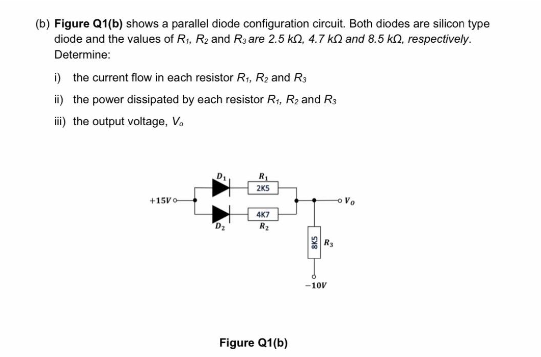
Transcribed Image Text:(b) Figure Q1(b) shows a parallel diode configuration circuit. Both diodes are silicon type
diode and the values of R₁, R₂ and Rare 2.5 k2, 4.7 kand 8.5 kn, respectively.
Determine:
i) the current flow in each resistor R₁, R₂ and R3
ii) the power dissipated by each resistor R₁, R₂ and R3
iii) the output voltage, V.
+15Vo
Di
D₂
R₁
2K5
4K7
R₂
Figure Q1(b)
5x8
-10V
Vo
Expert Solution
This question has been solved!
Explore an expertly crafted, step-by-step solution for a thorough understanding of key concepts.

Step by step
Solved in 3 steps with 3 images

Knowledge Booster


Learn more about
Need a deep-dive on the concept behind this application? Look no further. Learn more about this topic, electrical-engineering and related others by exploring similar questions and additional content below.Recommended textbooks for you
Power System Analysis and Design (MindTap Course …
Electrical Engineering
ISBN:
9781305632134
Author:
J. Duncan Glover, Thomas Overbye, Mulukutla S. Sarma
Publisher:
Cengage Learning


Electricity for Refrigeration, Heating, and Air C…
Mechanical Engineering
ISBN:
9781337399128
Author:
Russell E. Smith
Publisher:
Cengage Learning
Power System Analysis and Design (MindTap Course …
Electrical Engineering
ISBN:
9781305632134
Author:
J. Duncan Glover, Thomas Overbye, Mulukutla S. Sarma
Publisher:
Cengage Learning
Electricity for Refrigeration, Heating, and Air C…
Mechanical Engineering
ISBN:
9781337399128
Author:
Russell E. Smith
Publisher:
Cengage Learning

Delmar's Standard Textbook Of Electricity
Electrical Engineering
ISBN:
9781337900348
Author:
Stephen L. Herman
Publisher:
Cengage Learning