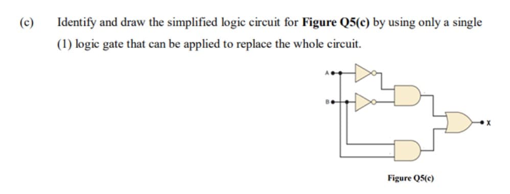
(c) Identify and draw the simplified logic circuit for Figure Q5(c) by using only a single (1) logic gate that can be applied to replace the whole circuit. Figure Q5(c)
Q: Problem 2: Plot the frequency response (magnitude and phase) of the system: 3000(s+2) G(s) = s(s+5)²…
A:
Q: 3. The open loop transfer function of unit feedback system is given. The specification for the…
A:
Q: A 10 kW, 400 V, three phase balanced delta connected load has a power factor of 0.8. What is the…
A: Given three phase balanced delta connected load has, Power rating, P=10 kW. Voltage rating,…
Q: snip
A: (a) There are nine tasks A1, A2, A3, B1, C1, C2, D1, D2, and E1, the precedence diagram is shown as
Q: PROBLEM 7 A telephone network has a bandwidth of 3.4 kHz. (a) Calculate the capacity of the channel…
A: Science and engineering employ the signal-to-noise ratio as a metric to evaluate the strength of the…
Q: give me dc or ac motor that can be assemble easily like electric fan
A: Electric fan: Electric fan is an electrical appliances that is used for the circulation of air in…
Q: A capacitor is made with a polymeric dielectric having an & of 2.26 and a dielectric breakdown…
A:
Q: Find the even and odd parts of the signal x(t) = 2(t² + 3t+2) cos(t).
A:
Q: A transmission loss of 33 MW is incurred if 115 MW is transmitted from plant 1 to the load. Find the…
A: Given, Transmission power loss, Ploss=33 MW. Transmitted power from plant 1, PG1=115 MW. The value…
Q: A 28 KVA 20k/480V 60 Hz distribution transformer is tested with the following results. Open circuit…
A: Given that: Distribution transformer S=20 kVA, 20k/480 V, 60 Hz. OC test: VOC=480 V, IOC=1.6 A,…
Q: 3) a. b. C. d. For the equation, F = (A = B) + A'C find the following The truth table for F The…
A:
Q: Q-A 220 V, DC shunt motor is operating at a speed of 1440 rpm. The armature resistance is 1.0 22 and…
A: Supply voltage, VS=220 V operating speed, N=1440RPM armature current, Ia=10 A armature…
Q: An absorption line in a medium is represented by the imaginary part of the rel- ative permittivity…
A: The imaginary part of the relative permittivity is given as ∈''r = Aδv - v0 - Aδv + v0 Now, ∈r (ω)…
Q: Problem 1 Find the Thevening and Norton equivalent circuits for the network shown below. 5Ω www 4Ω…
A:
Q: What is the Boolean expression of the following combinational circuit? A B O (A.B). B O (A+B) + B O…
A: Given data, Expression is given as,
Q: 28. A three-phase load is to be powered by a three-wire, three-phase, Y-connected source having…
A: For any three phase balanced system we can analyze the circuit by analyzing any single phase only.…
Q: 1) A 12 KVA, 480/120 V transformer is tested to determine its equivalent circuit. The test results…
A:
Q: The current through an inductor with inductance 1 mH is given by i(t) = 0.1 sin 106t. Find the…
A: This is a problem of circuits. The detailed solution is given in the next step
Q: RT ≥2 3 4 M 1 M 2 M M W 3 4 FIND RT 1 M 2 M 1 M W 2 3
A: Concept used :- As circuit is formed with delta connection, so we will simplify it with delta to…
Q: A three-phase squirrel cage IM has a starting current of 10 times the full load current and full…
A: Given a three-phase squirrel cage Induction motor has, Starting current, Ist=10Ifl. Full load slip,…
Q: The Zener diode shown in the circuit has a current I₂ = 8 mA, at 8.8 V and resistance rz = 25 2. The…
A: Since you have asked multiple questions in a single request, we will be answering only the first…
Q: c) An audio signal 10sin 27(2000t) amplitude modulates a carrier 20sin 2л(200000t). i) ii) Determine…
A: Given: Audio Signal m(t) = 10sin2π(2000t) = Amsin(2πfmt+θ) Carrier Signal c(t) = 20sin2π(200000t) =…
Q: A resistor is connected to a 3.0 V battery: the power dissipated in the resistor is 1.0 W. If the…
A:
Q: Example 12.23. A voltmeter, ammeter and wattmeter are suitably connected to measure the power input…
A: Given the readings of the instruments, Voltage, V=110 V. Current, I=2.5 A. Total power loss, P=150…
Q: 220 V + ΖΩ M 20 M ORL pat 8 M 15 _M 12 M Find RN, IN, IL if R₁ = 50 Norton's theorem + 110 V
A:
Q: Given that ROCOF is 0.002. Find the number of failures and MTTF.
A: . SOLUTION GIVEN ROCOF = 0.002 ROCOF It is stands…
Q: Refer to the circuit shown in fig. 3, Apply circuit analysis techniques to find the voltage between…
A: Given data, Circuit diagram is given as,
Q: For the given circuit what is the value of X(s). V1 100V R1 1000 C1 0.001FF
A:
Q: In a three phase balanced Y-Y system, the source phase currents have a magnitude of 9 A. The…
A: Given, A 3-φ balanced Y-Y system with, Phase current magnitude, Iph=9 A.
Q: transfer function
A:
Q: What is the Boolean expression of the following combinational circuit? A P B O (A.B). B O (A+B) + B…
A: Given,
Q: 4.59 a) Make a series of source transformations to find the voltage in the circuit in Fig. P4.59. b)…
A:
Q: Find the transfer function for each operational amplifier circuit, G(s) = Vo(s)/Vi(s)
A: Given here opamp based circuit and asked to find the transfer function.
Q: As you know, if you put two DC voltage sources in series, you can provide a larger voltage to an…
A: when two voltage sources are connected in series, In case of DC sources , resultant voltage will be…
Q: Find the transfer function G(s) vi(t) R1 202 Vo(s) Vi (s) + L1 4H using Mesh analysis C1 HF 3F R2…
A:
Q: Question No. 12 The system X = AX + Bu with A is O O O stable and controllable stable but…
A: Given a system, X˙=AX+BU, With, A=-1202, B=01.
Q: 103. The nominal T' circuit of a transmission line has R = 10 2; X= 20 22 and Y = 400 µS for each…
A: Given: The nominal T circuit of a transmission line has, R=10 Ω.X=20 Ω.Y=400 μS. Impedance,…
Q: A given system has three sensors that can produce an output of 0 or 1. The system operates properly…
A:
Q: Given a transfer function H(w)= jw/(jw+1000), find the gain (in dB) at a frequency of 0.24 kHz.…
A:
Q: Example 9 By inspection, write the mesh-current equations for the circuit in Fig
A: For the given circuit, we have to write mesh current equations. We are considering mesh current I1,…
Q: A Single-phase transformer has a turns ratio 1: 2, and is connected to a purely resistive load as…
A: Given, A single-phase transformer has, Turns ratio, a=1:2. The magnetizing current, Im=1 A. The…
Q: 7. A Wheatstone bridge consists of AB=402, BC = 3 02. CD=622, and DA = 52. A 2 volt cell is…
A: Given: Find: Current through the Galvanometer = ?
Q: The time-domain signal shown in the top plot is comprised of the sinusoidal waveforms shown in the…
A: We know that Fourier transform of sin (2*pi*fa*t) is 0.5(dirracdelta (f-fa)-dirracdelta (f+fa)) In…
Q: For the circuit shown below VCB= 0.5V and ß= 100. The value of lo is +5 V Ic 0.5 -5 V 5 ΚΩ -O Vo 10
A: Given transistor circuit, VCB=0.5 V. β=100.
Q: 5. Find the equivalent resistance Rb for each of the circuits shown below:
A: We are authorized to answer three subparts at a time, since you have not mentioned which part you…
Q: A 200 V dc motor takes 50 A in series and is operating at a speed of 1000 rpm when full of…
A: Given, A dc motor with, Terminal voltage, V=200 V. Armature current, Ia=50 A. Operating speed,…
Q: In the inverting amplifier of Figure 18.5, R; = 1k№ and Rƒ=2kM. Determine the out- put voltage when…
A: Inverting resistance Ri = 1 kΩ Inverting resistance Rf = 2 kΩ We have to determine the output…
Q: The op amp in the circuit in (Figure 1) is ideal. Take R = 56 ΚΩ. Figure + 6ΚΩ Μ 120 mV 20 ΚΩ < -9V…
A:
Q: C. A hydro-electricity power plant operates under an effective head of 50m and a discharge of 94m³/…
A: Given data, Density of water ρ=1000 kg/m3 Effective head h = 50 m. Acceleration due to gravity g=9.8…
Q: 10. When there is 12 mA of current through a 1.2 k resistor, the voltage across the resistor is
A: It is given that: I=12 mAR=1.2 kΩ
Step by step
Solved in 2 steps with 3 images
- Use the equivalent NAND gate logic to convert the logic diagram in Figure 5.1 below to only contain NAND gates. Redraw the logic diagram with input/output labels.Define Combined (Combinational) and Extraordinary (Sequential) Logic circuits with the figure, explain brieflyDraw in Table 3 the circuit schematic of each segment using the basic logic gates in kmap
- Describe in a short paragraph the difference between combinational logic circuits and sequential logic circuits.Q5. (a) Convert the following logic gate circuit into a Boolean expression, writing Boolean sub-expressions next to each gate output in the diagram: (b) Realise Ex-NOR gate using universal gate?Rewire these two logic gate diagrams as circuits with IC (integrated circuit) Chips.
- The ASM chart shown in Figure 4 specifies a synchronous sequential logic circuit. Derive a suitable state table from the ASM and design the circuit for the state table using JK flip-flop and logic gates.Define Combined (Combinational) and Adisyl (Sequential) Logic circuits.Convert the BCD to Excess-3 converter to its NOR gate equivalent form. Draw the logic diagram (Not the IC diagram) of the minimized NOR gate equivalent circuit (Give me the answer correctly and calculation also )