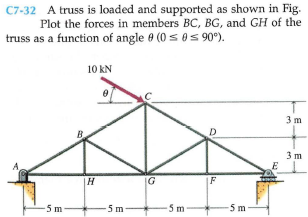
C7-32 A truss is loaded and supported as shown in Fig. Plot the forces in members BC, BG, and GH of the truss as a function of angle e (0 s 0s 90°). 10 kN 3 m D 3 m |F 5 m -5m -5m -5m
Q: P4-1. Draw the free-body diagram of object. 600 N m -2 m- 3m
A: Given data Applied moment = 600Nm To draw the free body diagram of the object with given moment
Q: Please write down each step clearly. Draw free-body diagrams of members AC and BG 3 m 8 m 2 m 15 2 m…
A:
Q: The link in the figure is weightless. Block A has a mass of 185 kg, and block B has a mass of 65 kg.…
A:
Q: The jib crane is designed for a maximum capacity of 5 kN, and its uniform I-beam has a mass of 200…
A:
Q: Calculate the magnitude of the tension T and the angle for which the eye bolt will be under a…
A:
Q: Draw the free-body diagram of CBA and DB
A:
Q: is formed in a quar- C6-67 The lever shown in Fig. ter circular arc of radius 20 in. Plot A and B,…
A: Where, FB = force acting at joint B. RX = horizontal reaction at A RY = vertical reaction at A
Q: C6-71 The hydraulic cylinder BC is used to tip the box of the dump truck shown in Fig. P6-71. If the…
A: From the above figure,
Q: The operation of the fuel pump for an automobile depends on the reciprocating action of the rocker…
A:
Q: 6-45 A rope and pulley system is used to support a body as shown in Fig. the ropes are continuous…
A: Drawing the FBD of the rope and pulley as shown below –
Q: The jib crane is designed for a maximum capacity of 7 kN, and its uniform I-beam has a mass of 160…
A: Given Maximum capacity = 7 kg Beam mass = 160 kg Eccentric range = 0.2m to 3.6 m To find Resultant…
Q: The member OBC and sheave at C together have a mass of 500 kg, with a combined center of mass at G.…
A:
Q: 15
A:
Q: 1- Construct a complete set of force polygons for the mech equilibrium shown in the figure, and if…
A: Given:
Q: 6-55* A rope and pulley system is used to support a body as shown in Fig. P6-55. Each pulley is free…
A: Consider the free body diagram of the pulley C as shown below, From the vertical equilibrium of…
Q: LECTURE 5- EXERCISES-2 FIND THE TRUE MAGNITUDE AND DIRECTION OF ALL THE MEMBER 1) FORCES IN THE…
A:
Q: Determine the force in member JH and BH for the truss loaded and supported as shown in figure (3).…
A:
Q: The jib crane is designed for a maximum capacity of 6 kN, and its uniform I-beam has a mass of 230…
A:
Q: P4-1. Draw the free-body diagram of object. 400 N/m -3 m -3m-
A: Given, UVL intensity = 400 N/m Converting UVL into Point Load = =12×Load×Length= 12×400×6=1200 N/m…
Q: MAKE A FREE BODY DIAGRAM A horizontal bar 10m long and of negligible weight rests on rough inclined…
A: Given Data The length of the bar is: L=10 m The angle of friction is: ϕ=15° The load acting at the…
Q: C7-31 Athree-bar truss is loaded and supported as shown in Fig. a function of angle e (0 ses 90°).…
A: Understand the following configuration for the triangular truss. From the given triangular truss.
Q: Neglecting friction and the weights of the members, compute the magnitudes of the pin reactions at A…
A: A pin support will exert both the horizontal and the vertical component of reaction forces. If a…
Q: *9-28. The linkage is made of two pin-connected A-36 steel members, each having a cross-sectional…
A: Given data: The material of the member of the linkage is A36 steel. The cross section of the member…
Q: In the fig. shown, compute the ff : D (11-13) the tension in cable BD 7.5 ft TBD = в (14-15) the…
A:
Q: P5-3. then draw the free-body diagrams of each member of the identify any two-force members, and…
A: If in an element no load or force is acting between the pins or hinge supports at both ends then…
Q: Determine the force p and friction force to kept the block (1000 N ) in equilibrium Fig (4). Figure…
A: W=1000 N
Q: The Figure shown below is the truss pattern proposed by engineering students for the one part of…
A:
Q: Make the free body diagram and calculate the reaction efforts at the points with movement…
A: Length, L1=1.9 m Length, L2=3.3 m Length, L3=3.5 m Load, P1=75 kN Load, P2=140 kN
Q: Q 10/Determine the force in member CK of the loaded truss. 1.5m 1.5m 1.5m 1.5mH G 3m- 1m M IN 2.25m…
A:
Q: and FJ of the pin-connected truss of Fig. P4-75. 6 6 2000" 4-75. Determine the forces in members CD,…
A:
Q: P4-1. Draw the free-body diagram of object. 30 400 N в. - 2 m 1m
A: In the given figure a beam shown which is fixed at point C and free at the point A. It is supported…
Q: Q 10/Determine the force in member CK of the loaded truss. 1.5m 15m H 1m -3m M IN /1.5m 1.5m G 2.25…
A:
Q: Determine the tension in the cable if W-100N. Negligible weights of members and friction. 0.9 m 1.8…
A: Given: The frame is shown below: W= 100 N
Q: C6-72 An extension ladder is being raised into position by a hydraulic cylinder as shown in Fig.…
A: Understand the following diagram for the configuration of the ladder and the hydraulic cylinder.…
Q: touch "ull43% D 20:51 MENG250 - Practice Ass.. 5 *5-88. Determine the horizontal and vertical…
A:
Q: The jib crane is designed for a maximum capacity of 6 kN, and its uniform I-beam has a mass of 190…
A: Note: Since you have posted a question with multiple sub-parts, we will solve first three sub-parts…
Q: The jib crane is designed for a maximum capacity of 14 kN, and its uniform l-beam has a mass of 270…
A:
Q: 6-46 A rope and pulley system is used to support a body as shown in Fig. the ropes are continuous…
A: Given data: Rope and pulley system mass of the body = 250 kg To determine:…
Q: d with plot its where *3-40. The load has a mass of 15 kg and is lifted by the pulley system shown.…
A: 1
Q: P5-3. then draw the free-body diagrams of each member of the identify any two-force members, and…
A: The two force members are member BC and member AB. The free-body diagram of the member AB is: Here,…
Q: A cantilever truss shown is subjected to a wind load of 4.32 kN/m normal to the roof surface. Use $1…
A: The reaction at G is 11.232 kN.
Q: 4/31 Determine the forces in members GH and CG for the truss loaded and supported as shown. Does the…
A:
Q: 0.1 m B 0.6 m Problem 8. Determine the magnitude and direction 0 of the minimum force P needed to…
A:
Q: he 4-kg smooth cylinder is supported by the spring having a stiffness of kAB = 120 N/m.
A: Givenm=4kgSpring constant KAB=120N/mforce=60N
Q: Mass of car: 1400 kg B H m- C -2 m- + 1.5 r Mass of trailer: 800 kg Braking force at C (uc= 0.40) is…
A:
Q: 6-49 Determine the force P required to push the 300-lb cylinder over the small block shown in Fig. P…
A: Given data: Weight of the cylinder = 300 lb The arrangement as shown in the…
Q: Determine the force in member JH and BH for the truss loaded and supported as shown in figure (3).…
A:
Q: YA A В L, =162 (57° L = 77 L, = 73 3. 027 X
A: given:
Q: 11-4.18. The bent bar ABC weighing 10 lb/ft is mounted as shown in Fig. P-11-4.18. upon a carriage…
A: Given: The bar weight, w = 10 lb/ft The carriage weight, W = 240 lb The load, P = 108 lb
Step by step
Solved in 4 steps with 2 images
- Draw the free-body diagram of CBA and DBShow the complete free body diagram for the problem.A 415 kg safe is hanging from the apparatus below. Determine the tension in the cable. Dimension a=1.9 m and dimension b=2.5 m. The mass of the beam is 85 kg. Use g = 10 N/kg. Hint: Take torques about the hinge and use the perpendicular lever arm version of the torque equation (the sin theta version will work but will require more calculation).
- Make the free body diagram and calculate the reaction efforts at the points with movement restrictions imposed. Data: L1 = 1.9m L2 = 3.3m L3 = 3.5m P1 = 75kN P2 = 140kNinclude also the free body diagramThe jib crane is designed for a maximum capacity of 14 kN, and its uniform I-beam has a mass of 270 kg. Plot the magnitude R of the force on the pin at A as a function of x through its operating range of x = 0.2 m to x = 4.0 m. On the same set of axes, plot the x- and y-components of the pin reaction at A. Do these plots on a separate piece of paper. Then answer the following questions in Wiley Plus as a check for your work. (You can disregard the plot, I only need a, b, c, and d)
- The jib crane is designed for a maximum capacity of 7 kN, and its uniform I-beam has a mass of 240 kg. Plot the magnitude R of the force on the pin at A as a function of x through its operating range of x = 0.2 m to x = 3.7 m. On the same set of axes, plot the x- and y-components of the pin reaction at A. Do these plots on a separate piece of paper. Then answer the following questions in Wiley Plus as a check for your work.(a) What is the value of R when x = 1.9 m?(b) What is the value of R when x = 3.2 m?(c) Determine the minimum value of R and the corresponding value of x.(d) For what value of R should the pin at A be designed?The homogenous bar A having a mass of 18 kg is 2 m long and is inclined at 60 degrees with the horizontal plane. The mass M of 7 kg is connected by the rope to the bar. The rope leaving the bar is horizontal. The coefficient of friction between the rope and the drum B is 0.20. What is the minimum coefficient of friction between the bar and the plane for equilibrium? Give solution. (Ans. coefficient of friction = 0.284)Draw the free body diagram of this problem
- A rear suspension system for a front wheel-drive vehicle is shown here. Spring EF is offset behind member CD. The normal force due to contact between the wheel and the road is 4200 N. Assume the weight of the wheel and suspension system components is negligible. Determine the magnitude of the member CD. Is the member in tension or compression? Determine the support reactions at A. Determine the unstretched length of the spring EF given a spring constant of 150 kN/m.A homogenous bar with length l and weight w lb rests horizontally as shown in Fig 9-37 with its free end on a block of weight W, the block W is at rest on a plane inclined at the angle α with the horizontal. Determine the necessary coefficient of friction μ between the block and the plane for equilibrium. Assume no friction between the bar and the block. Give solution. [Ans. μ=(sin 2α) / (w / W+2 cos2 α)]Find the stable equilibrium position of the system described in Prob. 10.56 if m = 2.06 kg.